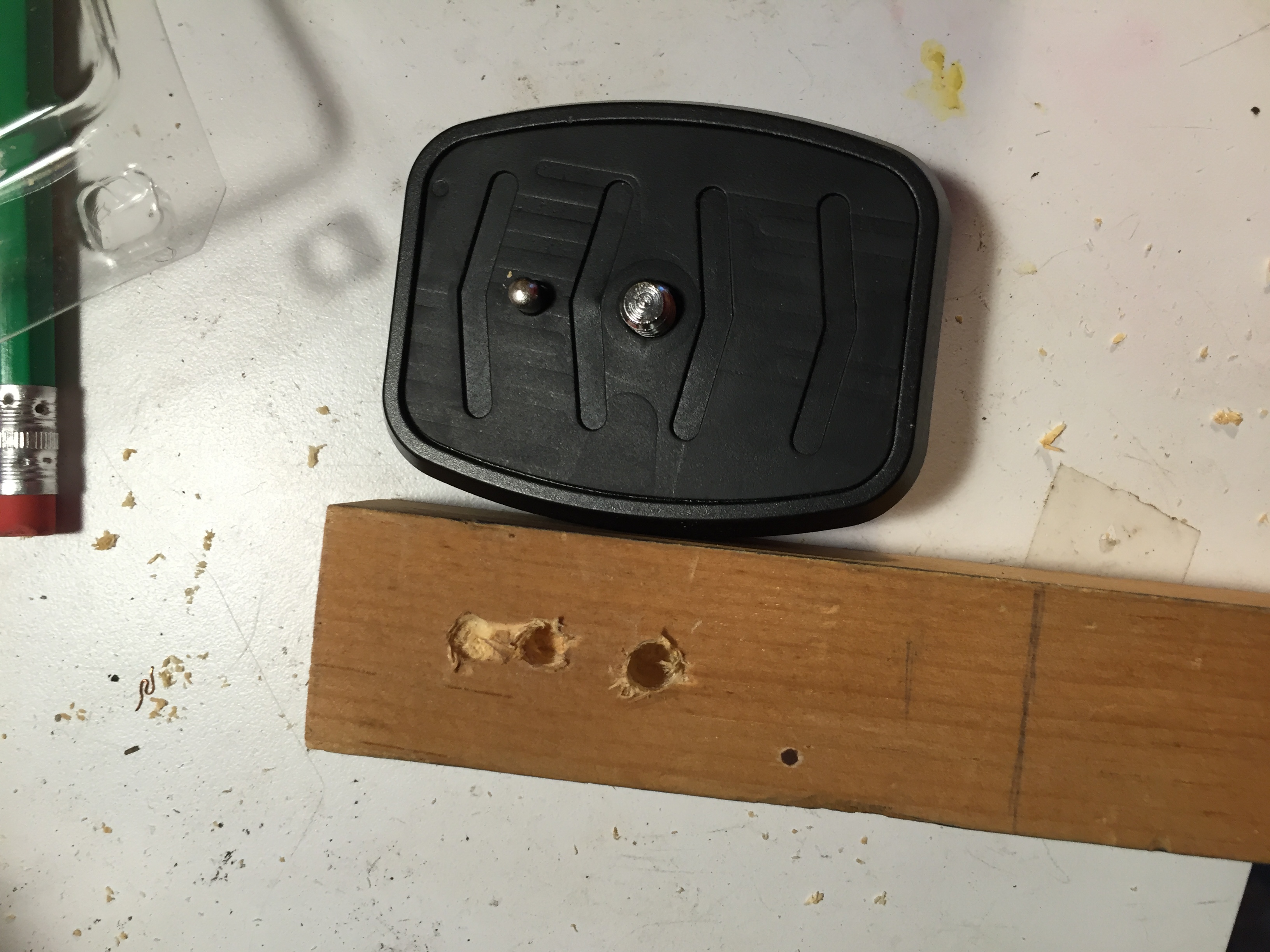
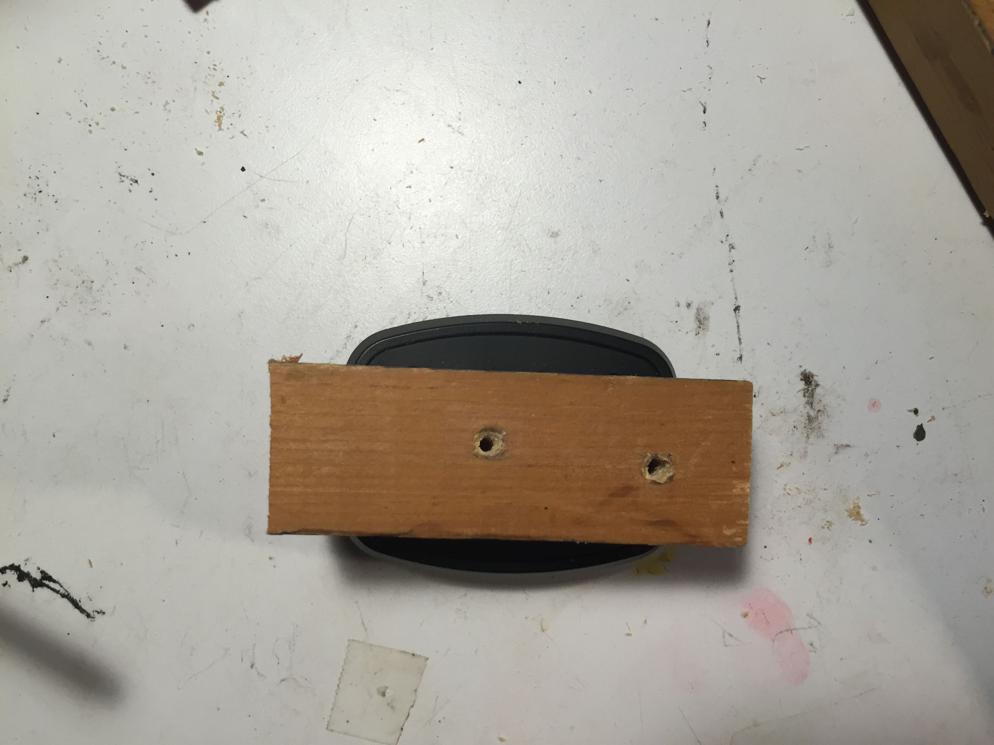
Starting with some scrap wood and a vague idea of what I wanted, I began to build my camera angle tester. I started with the tripod plate from my tripod and drilled two holes into the wood to align with the tripod screw and spring pin. Incrementally larger holes were key to a snug fit.
I could now use the tab on the underside of the tripod to screw it into the wood.
Protractors
I measured and cut a longer section of that same wood to match the length of my protractors. Fortunately, this wood was perfectly wide enough for both protractors to fit comfortably. 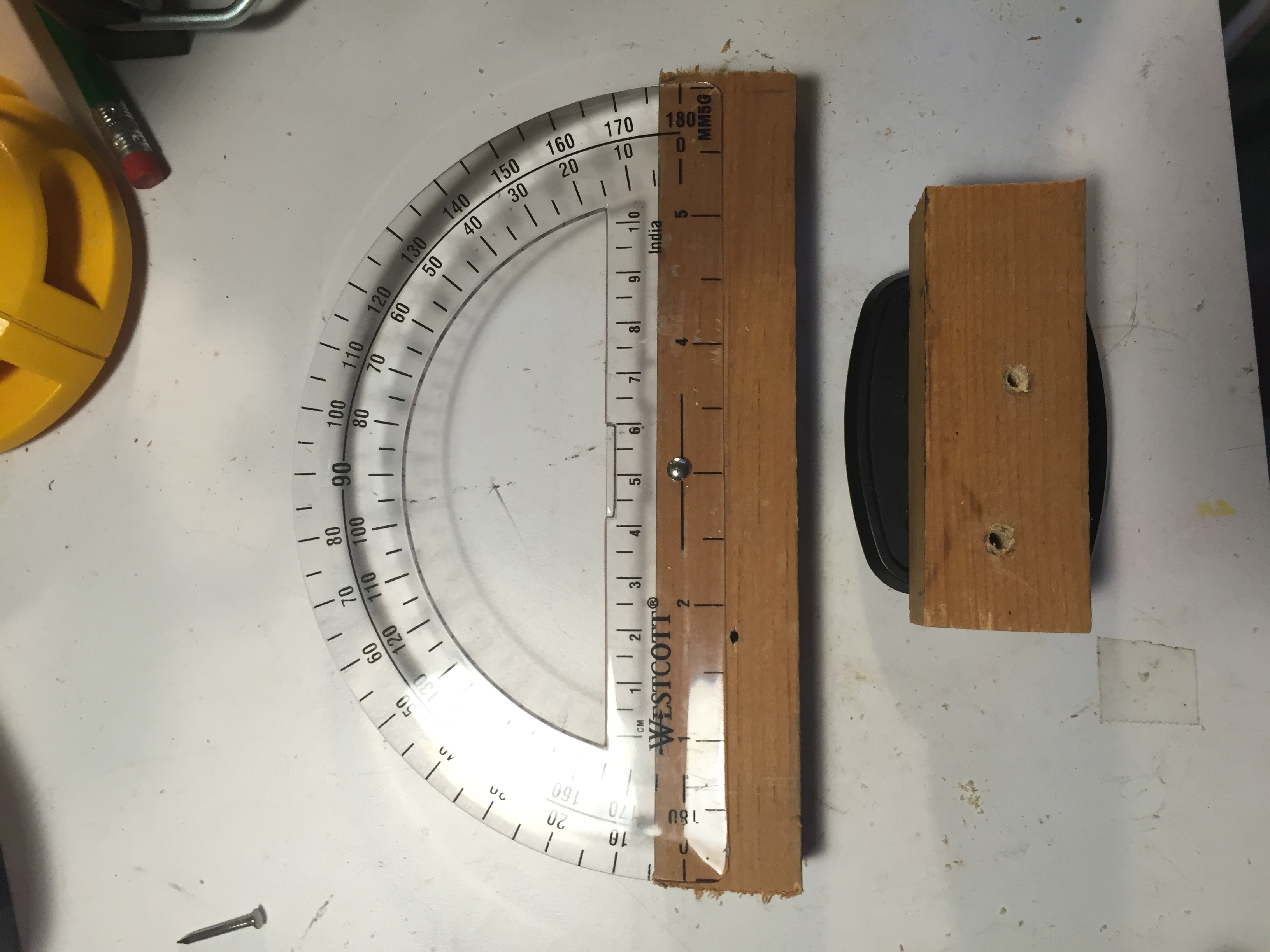
To affix the protractors, I nailed each of them to the wood through their center holes. With both tightly nailed in place and adjacent to each other, neither have room to swivel, so fortunately I did not need a second nail for each.
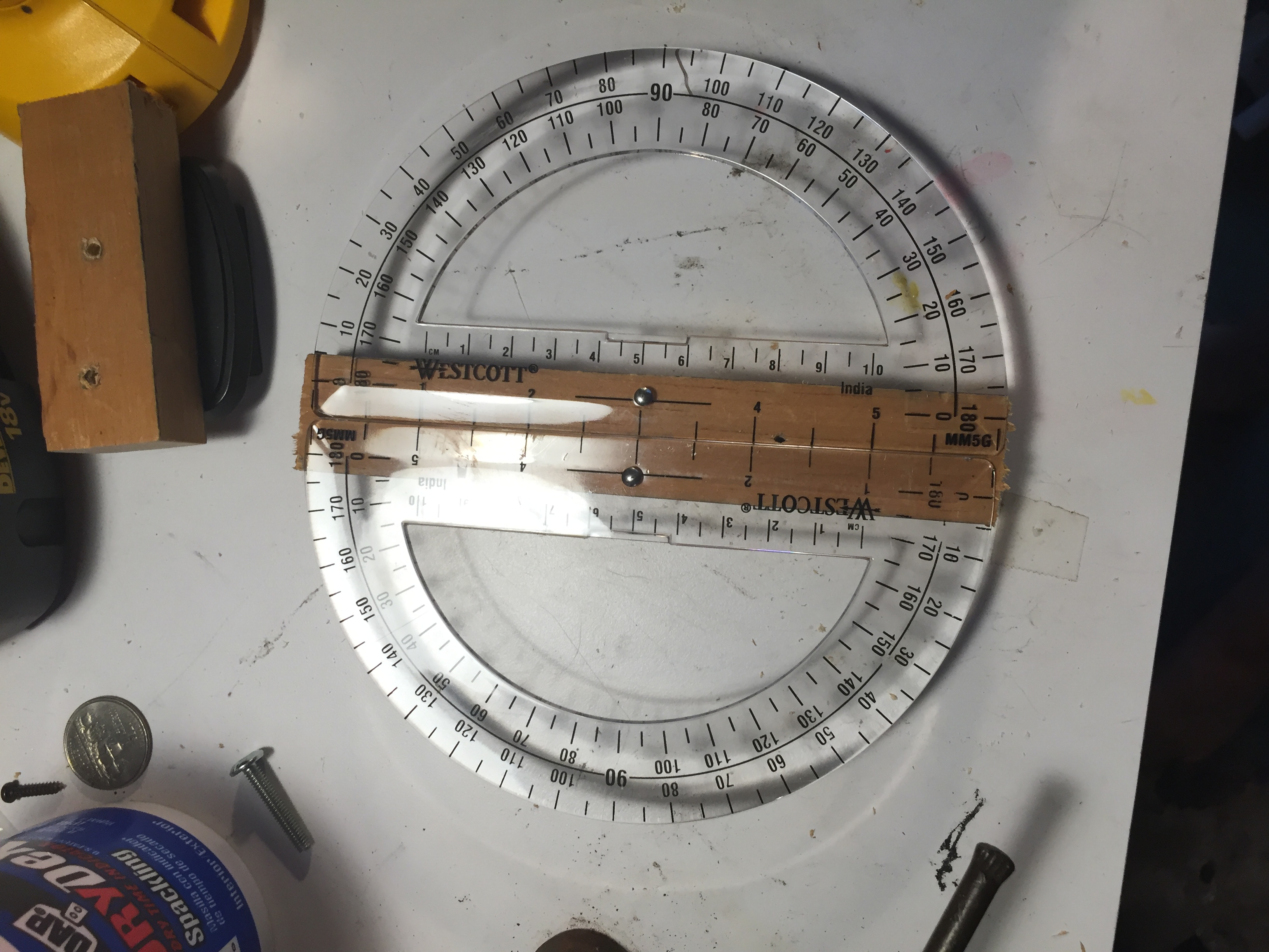
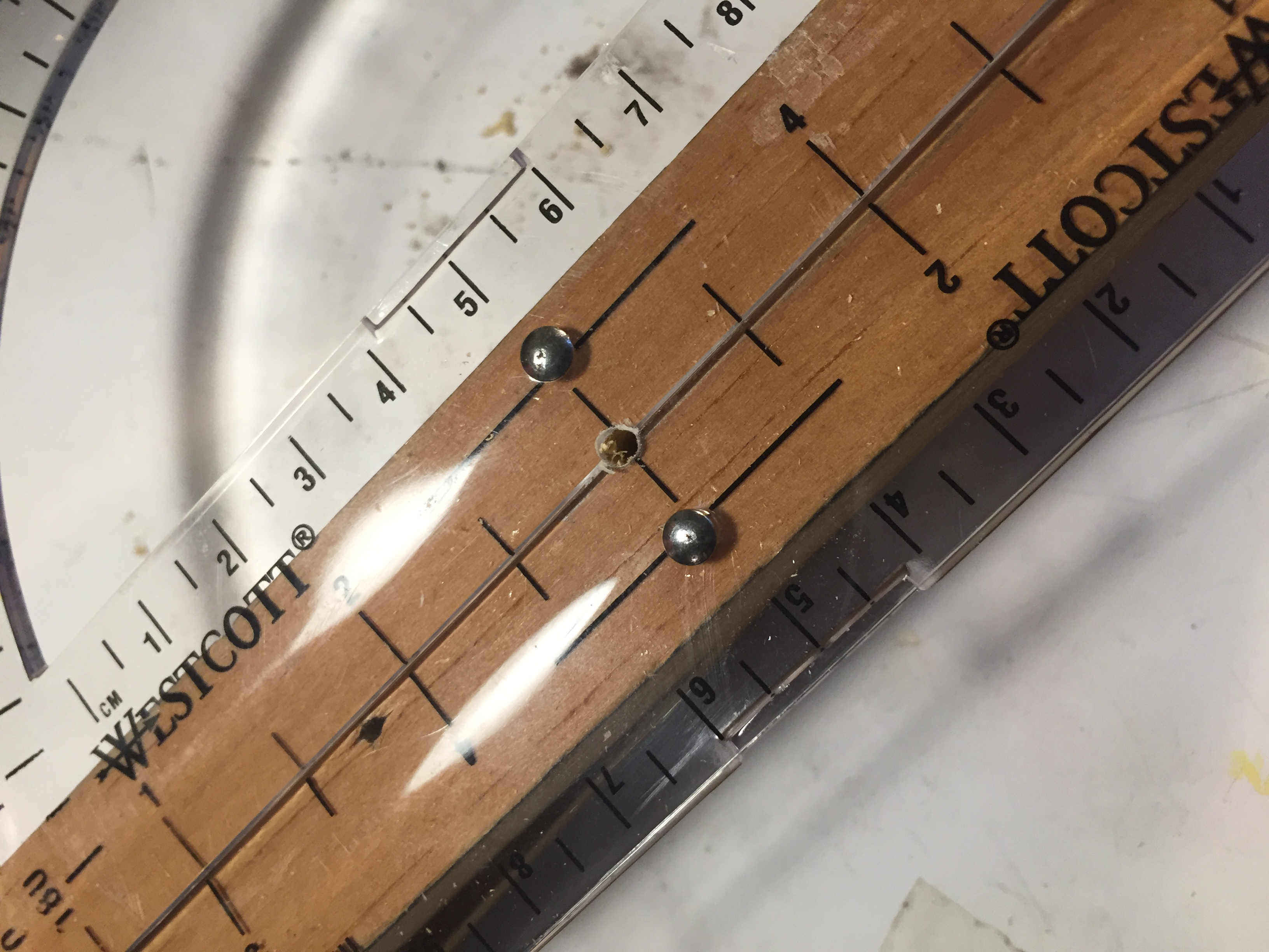
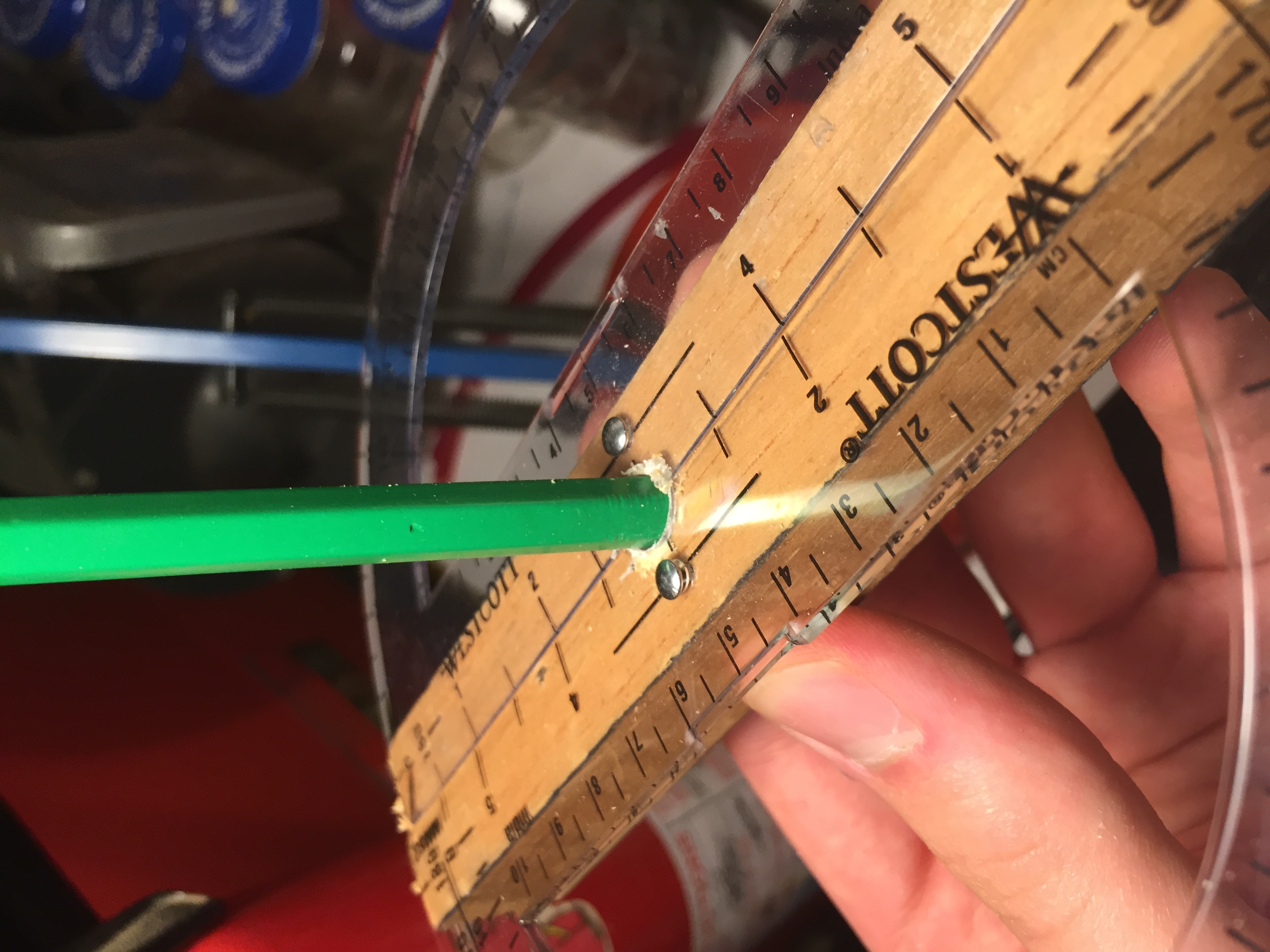
I needed a central axis to rotate the camera about, so I drilled incrementally larger holes in the center of the protractor. The picture above shows the first hole. This took several minutes of careful drilling to avoid cracking the protractors. For simplicity, I chose a standard pencil for my axis, and sized the hole accordingly. This center shaft originally only went about half way through the wood, but I later deepened it
Camera Mount
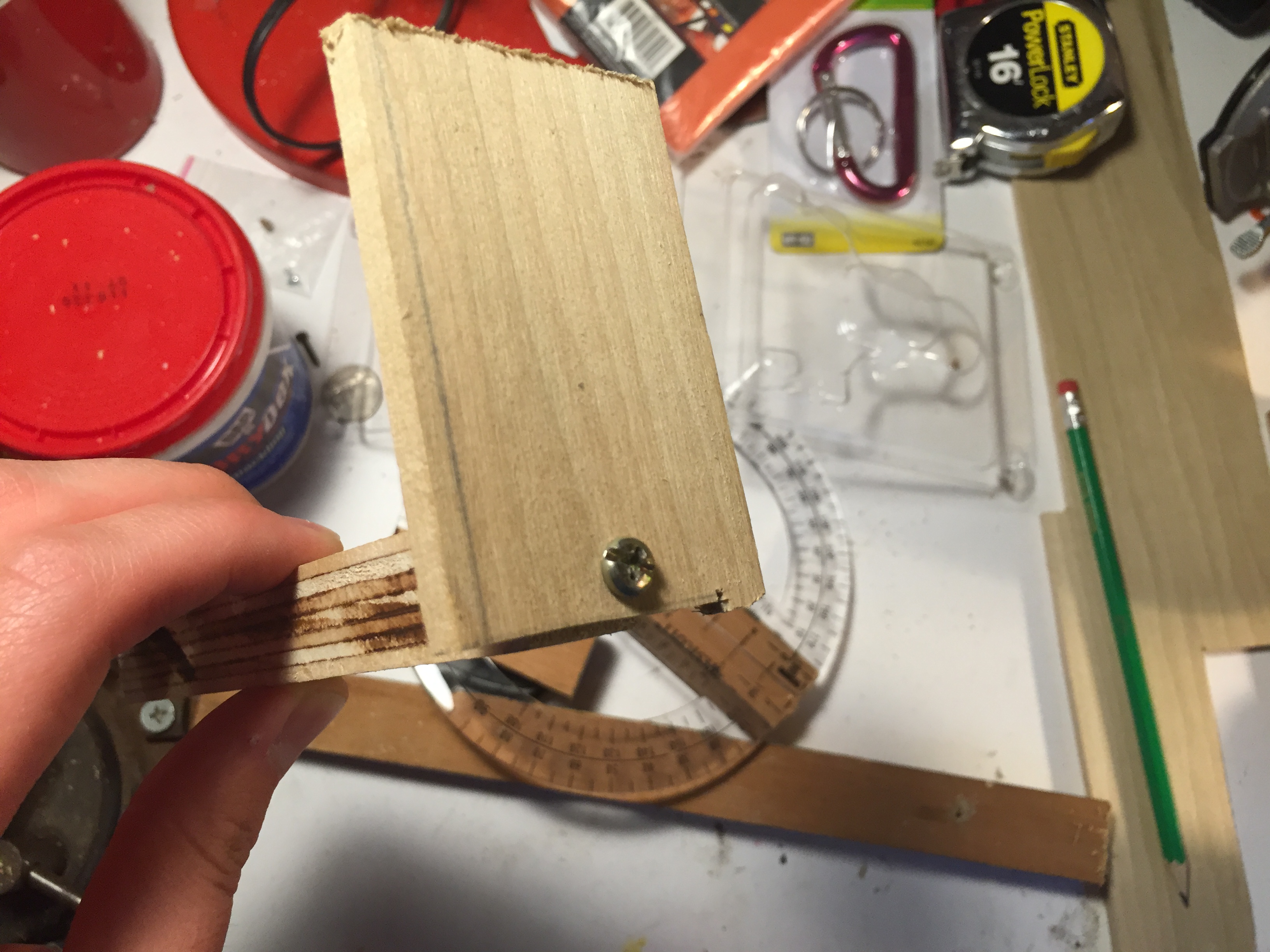
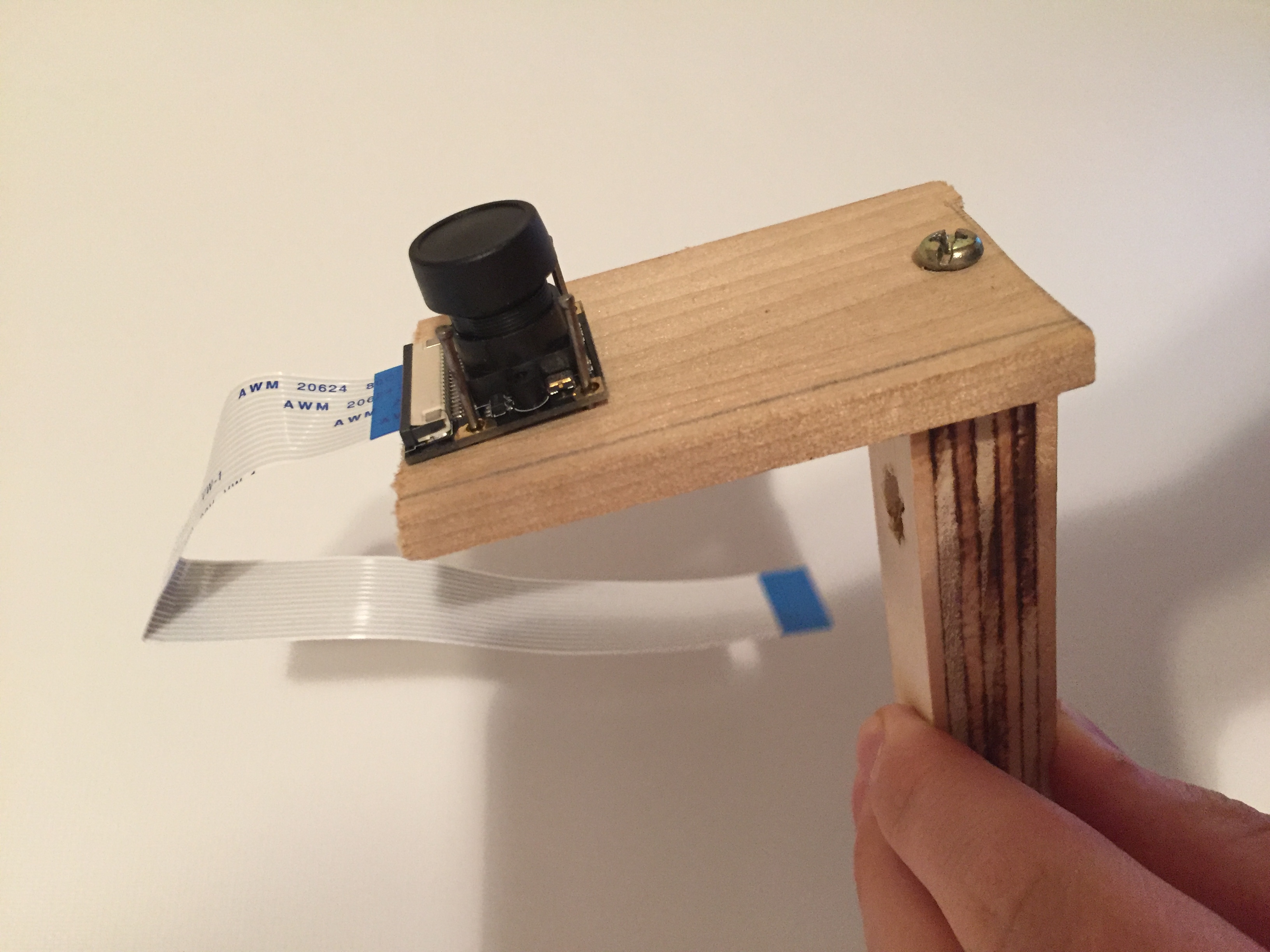
My original plan for this part envisioned an extended arm for the camera to attach to, and I followed this as closely as I could with the scrap wood.
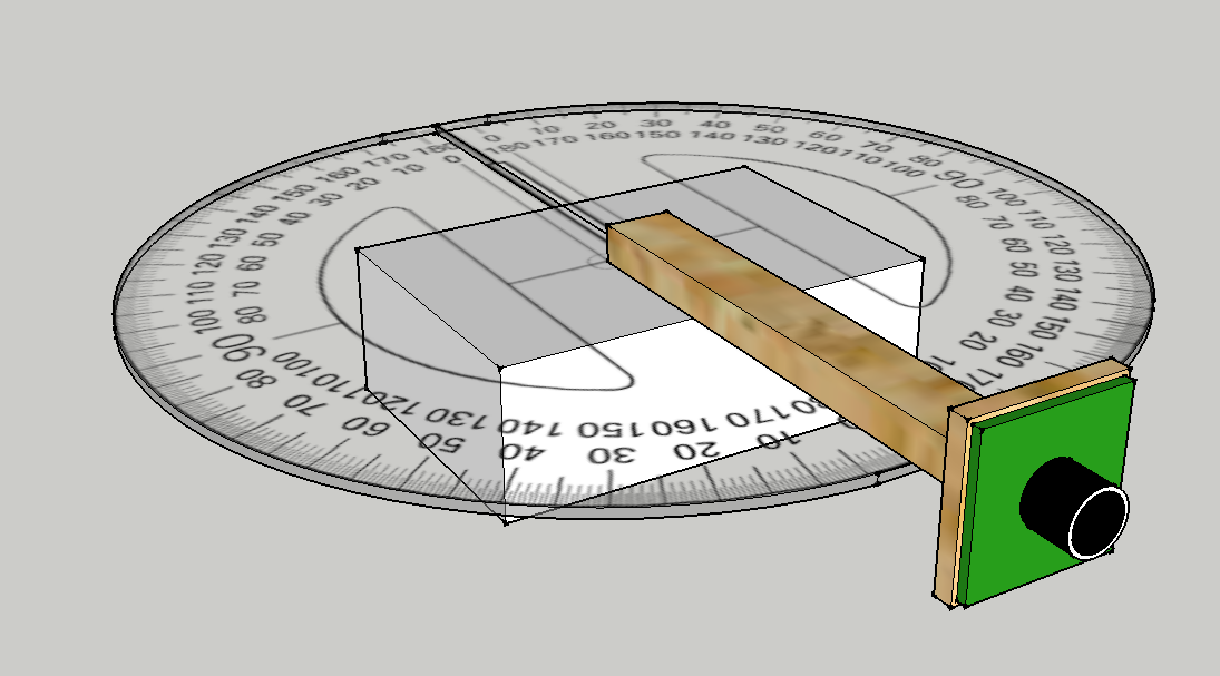
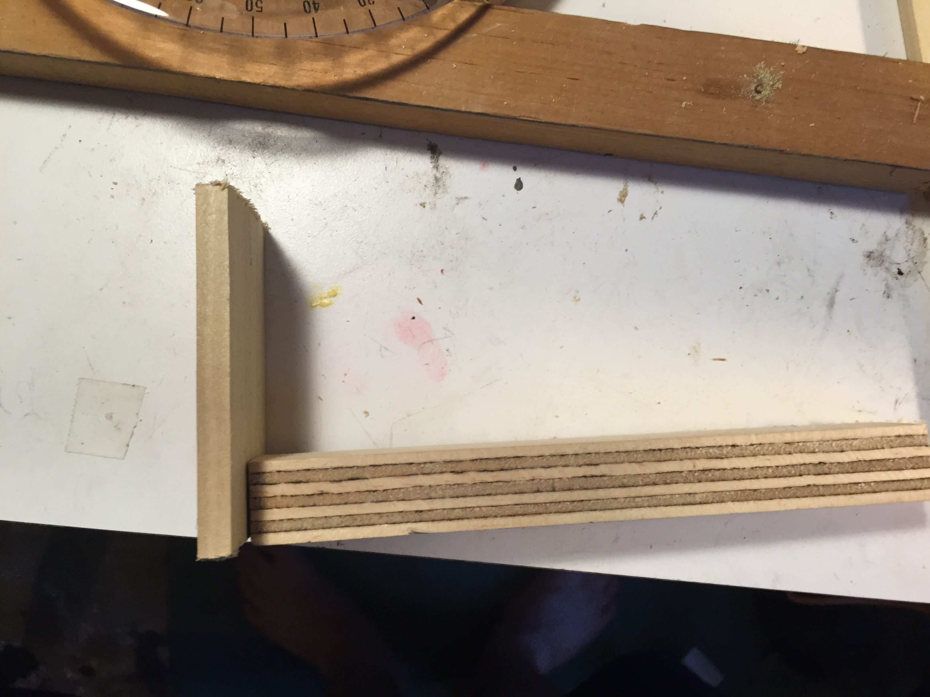
Using some leftover plywood and a jigsaw, I cut a very rough rectangle, more than twice the size of the camera. In hindsight, this piece was probably bigger than necessary. I didn’t want the camera anywhere near the sawdust, so I approximated its size, and left plenty of room for error. This plate I mounted on a wooden arm with a single screw. I then replicated the central axis hole in the arm.
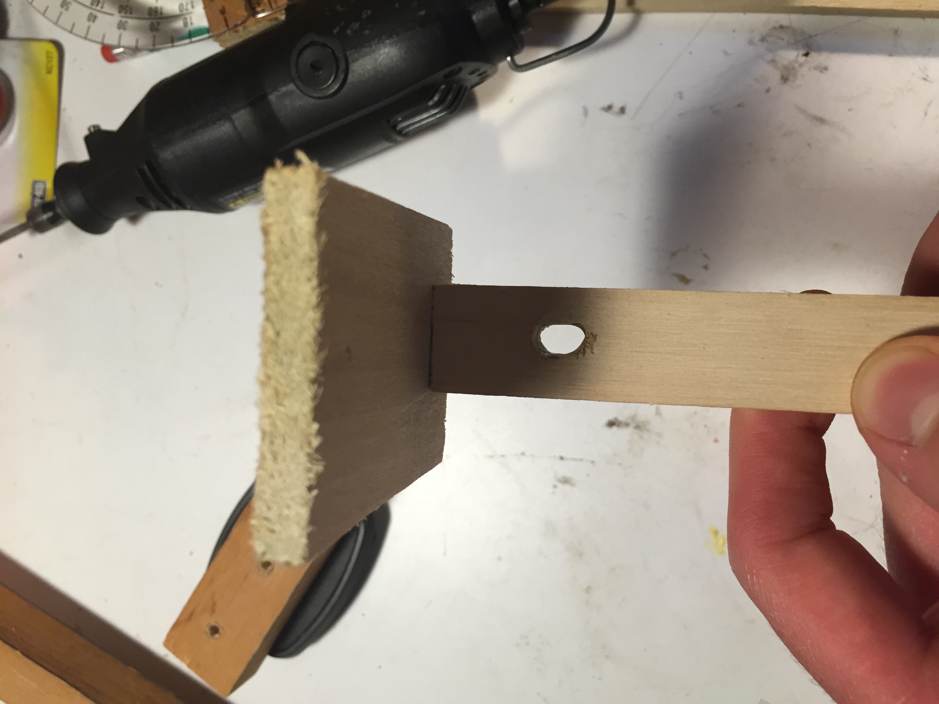
Importantly, I needed to be able to see what angle the camera was directed at. I had planned to look over the camera arm at the protractors and approximate the angle, but then realized I could do better. I made a small hole with the drill and then widened it with my Dremel (and a VERY dull routing bit).
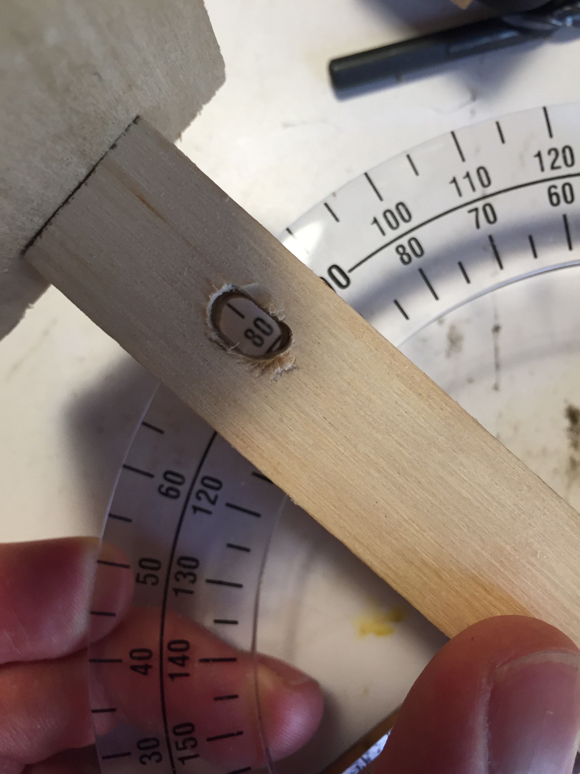
With the arm on the protractor base, I can now easily read the angle!
The Raspberry Pi Camera has 4 holes in the corners for mounting. 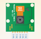
Using the camera as a template, I marked and then hammered in headless nails. I did not hammer with the camera there. 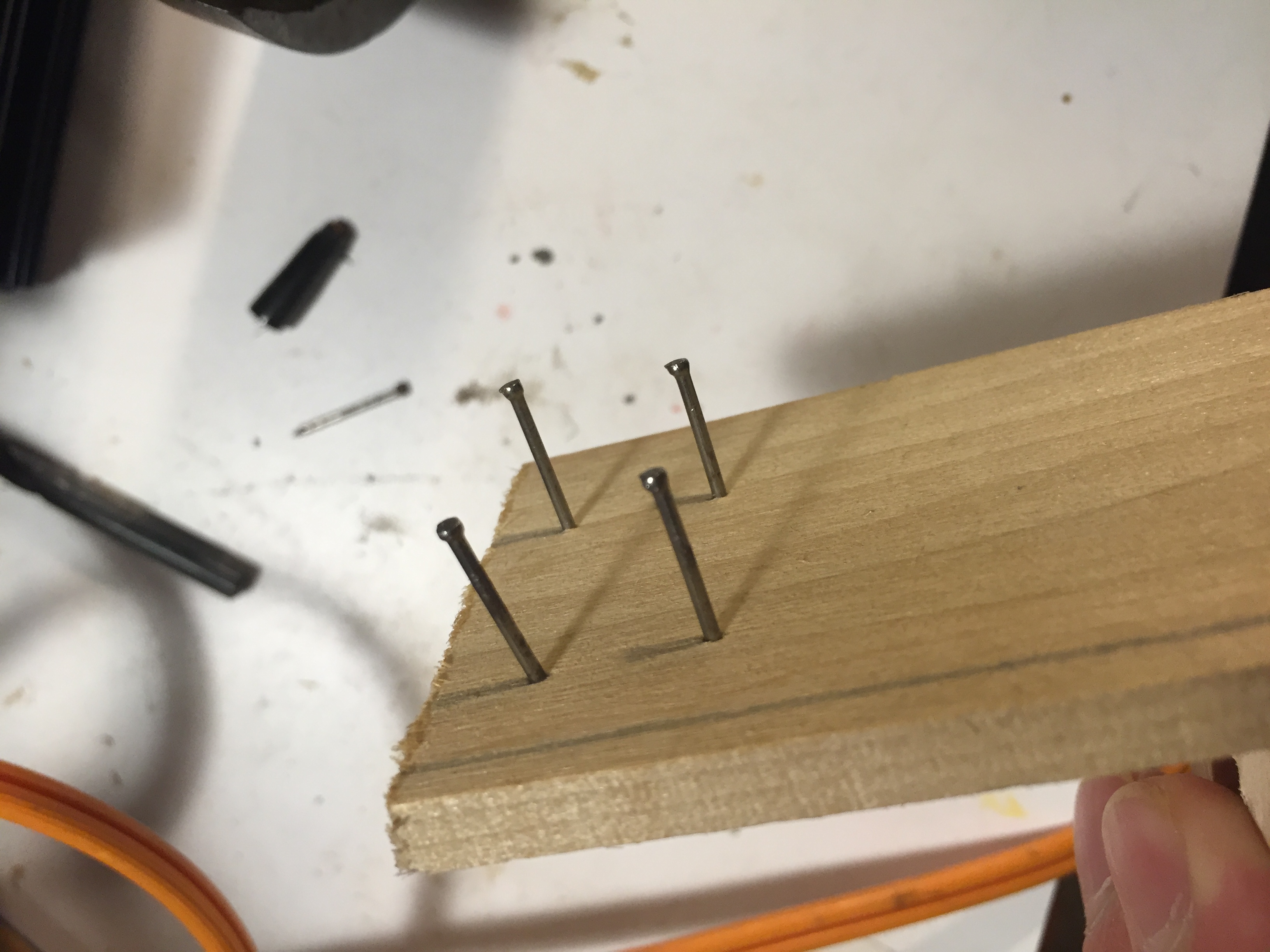
The camera was a perfect fit.
Using some more scrap plywood, I built a rough platform for the Pi and breadboard to sit on, and screwed it into the arm.
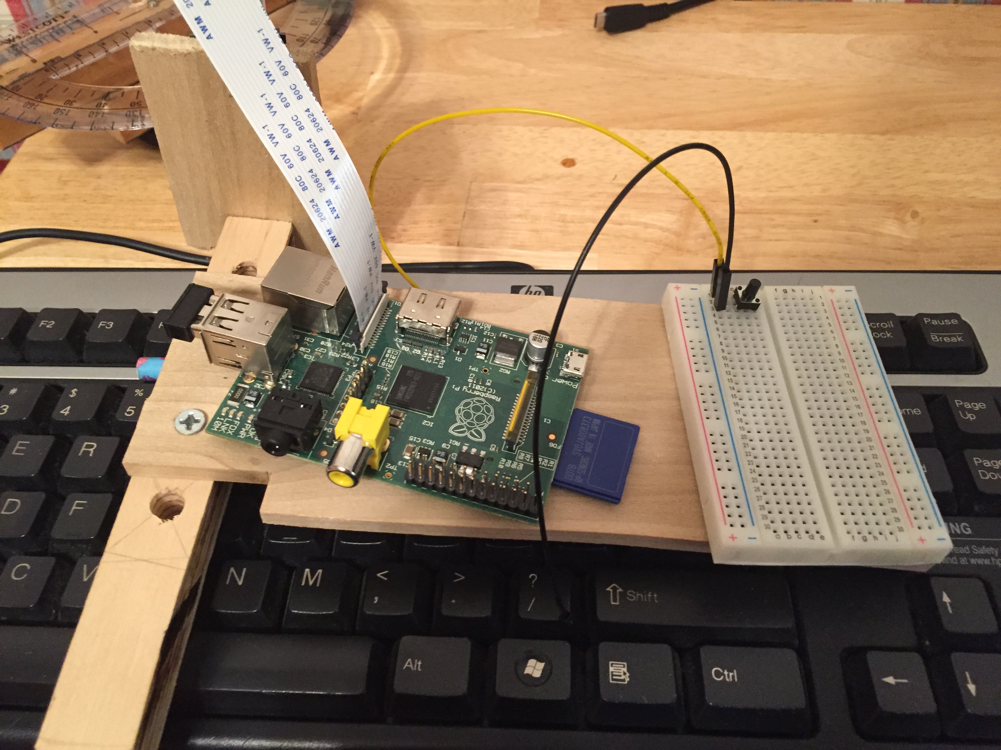
The whole apparatus is a bit off balanced, but it should work long enough for me to do the testing I need to do. I deepened the central axis hole to give the arm a deeper anchor and offset the unbalanced weight. When fully assembled, it seems sturdy enough for me to use.