Table of Contents
Intro
This project was part of my ENPM662 – Introduction to Modeling course at the University of Maryland. The project entailed selecting a robot and an appropriate task and then working through several of the modeling components for that task. This project was a joint effort with my colleague Shantam Bajpai.
Motivation
This project explores a pick and place robot used for inventory management. Placing and retrieving items from a warehouse are boring repetitive tasks that can be easily automated, freeing humans to do more interesting work. The applications of this technology are wide – many companies (especially large scale retailers like Amazon) have vast warehouses with their supplies/goods. Robots can operate in the warehouse 24 hours/day, 7 days/week, 365 days/year. They will never get sleepy, fatigued, injured or sick. The robots’ resolute tirelessness make them much more efficient than humans, who usually work in 8 hour shifts, 5 days/week, 50 weeks/year, and are prone to injury and illness.
Robot Info
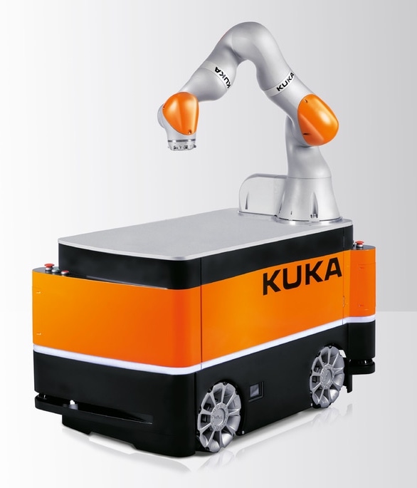
The robot (KUKA KMR iiwa) consists of two systems. The base is an omnidirectional (mecanum) wheel cart with 3 degrees of freedom – it can move in any direction in the floor plane. Rigidly mounted on the cart is a KUKA LBR iiwa 14 R820. The KUKA arm is a 7 DOF serial manipulator consisting exclusively of revolute joints.
The circular base of the manipulator arm is tangential to the midpoint of the back edge of the cart.
Additional information about this robot system can be found here: https://www.kuka.com/en-us/products/mobility/mobile-robot-systems/kmr-iiwa
This robot system is built for inventory management and item retrieval. It is used within KUKA’s facilities for exactly this purpose. The redundant manipulator arm gives the robot sufficient degrees of freedom to reach it’s entire workspace in multiple configurations, allowing it to avoid minor obstacles (ex: shelves) while it works and pick up objects in different orientations. The mecanum wheel base allows the robot to achieve holonomic motion. It can move forward, backward, left, right, or on any planar diagonal with equal ease. It can also turn about it’s center or about it’s corners.
The Task
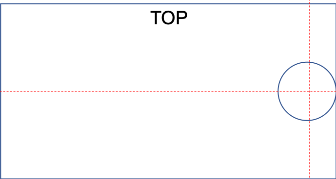
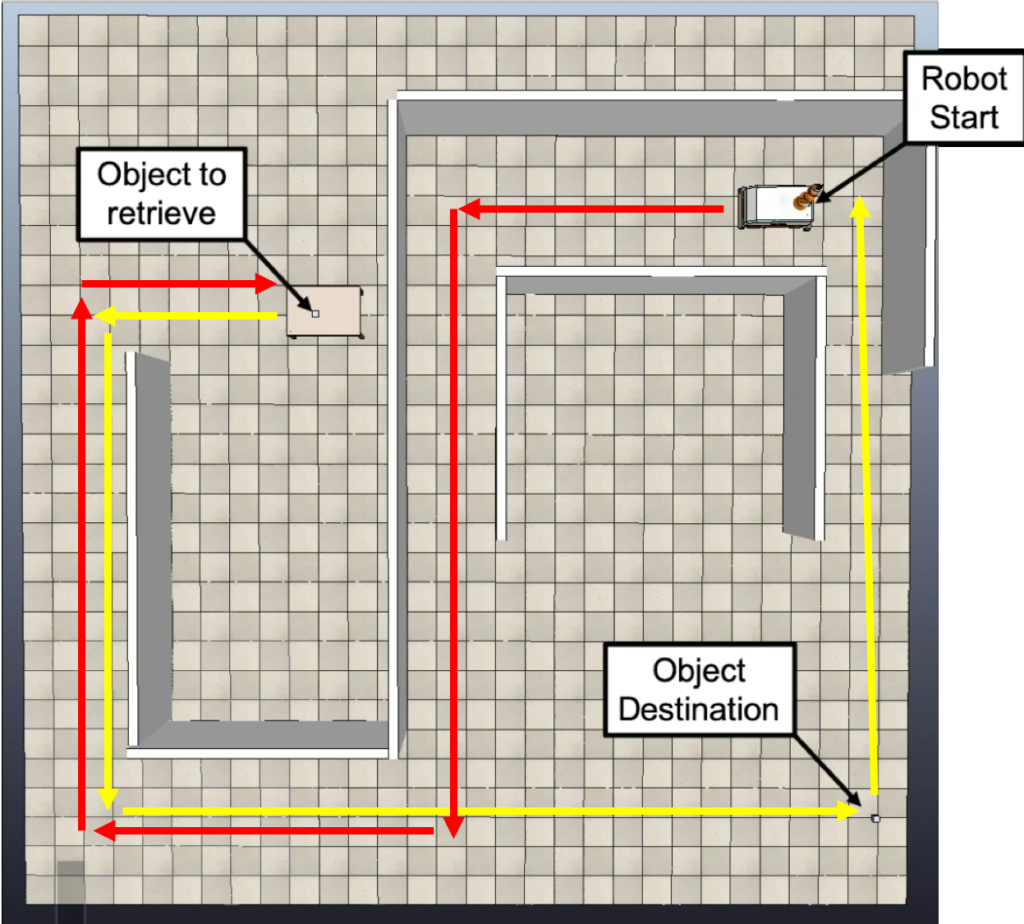
The robot rests, inactive, in it’s charging dock awaiting a task. This is the robot’s home position and the origin of it’s world frame. It will wait here until it is needed. Suddenly, the robot receives a signal from the control system with it’s new mission. The data contains key information – the item that must be retrieved, it’s location and orientation in the warehouse, it’s retrieval orientation/direction (if any), where it needs to be brought, and it’s deposition orientation/direction (if any). To make the robot’s life more challenging, the item to retrieve is in another room. Let’s say the warehouse looks something like this:
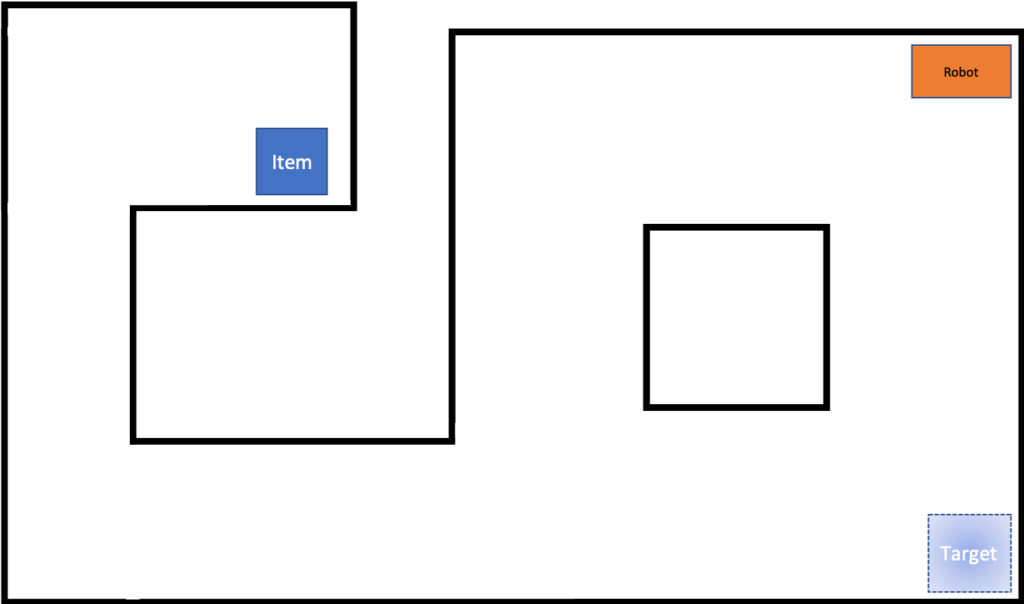
The black lines are walls that the robot cannot cross. The robot must:
- Leave it’s charging base (in a specific direction)
- Navigate through room 1
- Navigate through the hallway to room 2
- Navigate to the item
- Position the end effector so that it’s position and orientation matches that of the object. The robot may potentially need to avoid a shelf.
- Pick up the object. The object may have some specific retrieval orientation/direction, like a disc on a spindle.
- If the object has a required orientation for transport (like an open box or glass of water), the robot must maintain that end effector orientation while it moves.
- Navigate out of room 2 and back into the hallway
- Navigate through the hallway back to room 1
- Navigate to the target repository. This is where the item will be deposited.
- Deposit the object. (The object may again have a specific deposition orientation/direction, like a disc into a slot)
- Return to base and await further instructions.
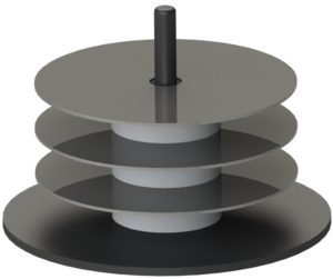
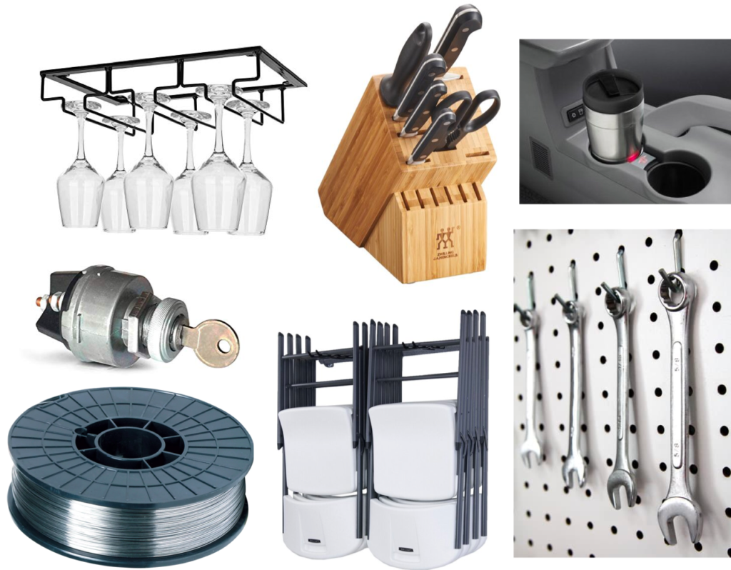
This area of the warehouse is robots only. It’s deep in the basement and very few humans ever go down there. We won’t need to worry about actively recognizing and avoiding those pesky fleshy moving obstacles. This tireless robot is the only one that works in this room, so it doesn’t need to avoid any other robotic moving obstacles. If it had companions, we’d rely on a centralized control system to track where each robot is and plan their paths accordingly to avoid collisions. The item to retrieve is described throughout this page as a disc on a spindle. This serves as an easy to reference example but it’s applicability may not be readily obvious. (You certainly could use this system to retrieve your favorite DVD from a standard disc spindle and stick it in the player, but that’s a pretty niche use case.) The disc is a simplified type representative of more useful items – It would be easy to swap such a disc with a spool of filament for 3D printing, a spool of metal wire for fabrication, or other similar geometries. The general case of objects with a specific retrieval/deposition orientation is not limited to just discs either; any object in a mount could be retrieved/deposited with similar methods. Some examples include:
- Disc on a spindle
- Spool on a spindle
- Wine glasses in a rack
- Knives in a knife block
- Key into a lock
- Cup in a cup holder
- Chairs from a rack
- Tools on a pegboard
and many many more!
Model Assumptions
We’ve made a number of assumptions to simplify the problem. These should all be sufficiently reasonable within the scope of the defined task.
- The warehouse floor has sufficient friction that the wheels can roll without slipping (no positional error in the floor plane).
- All bodies are perfectly rigid, there is no slip or backlash in gears, and motors have access to any required torque.
- The robot has sufficient technology (LiDAR, differential GPS, ultra-wide band radio triangulation, beacons, landmarks, visual tracking, etc.) that it can know it’s exact position and orientation within the warehouse at all times, and it already knows the layout/floor plan of the entire warehouse and its contents. Actually, if we assume perfect lossless movement without slippage and a known start position, dead reckoning will be sufficient to satisfy the known position/orientation.
- The warehouse ceiling is high enough to allow for the full robot workspace and offers no restrictions on the robot’s range of motion.
- The cart is heavy enough that the center of mass of the system is always within the convex hull support polygon of the wheels, making the system statically stable. The cart should never tip or have less than 4 wheels on the ground.
- The warehouse floor is perfectly flat and level. There are no inclines, ramps, hills, bumps, stairs, or floor defects the robot will need to deal with.
- The item to retrieve is perfectly rigid and non-deformable (no limit on gripper force used)
- The item to retrieve has a constant mass and constant mass distribution
- The gripper/object interface has a constant coefficient of friction
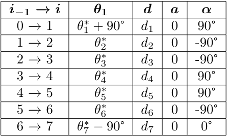
Forward Kinematics
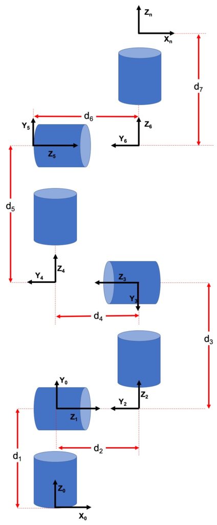
We used the joint diagram and the Denavit–Hartenberg convention to produce a DH table for the manipulator. We use the DH table to create A matrices and then multiply them all together to get the total forward kinematics. The cart has mecanum wheels, whose repeatable motions easy to codify, but don’t work as nicely with the DH table. To resolve this, we’ll set the base frame of the cart coincident with the manipulator base frame, instead of using the world base frame. This allows us to move the cart and arm independently, where the cart operates in the true world frame, and the manipulator operates in it’s own local base frame. The position of an object to be retrieved is therefore first defined in the world frame and then redefined in the robot frame once the object is within the manipulator’s work space.
A Matrices
$$Rot_{z_i}=\begin{bmatrix} cos(\theta_i) & -sin(\theta_i) & 0 & 0\\ sin(\theta_i) & cos(\theta_i) & 0 & 0\\ 0 & 0 & 1 & 0\\ 0 & 0 & 0 & 1 \end{bmatrix}$$ $$Trans_{z_i}=\begin{bmatrix} 0 & 0 & 0 & 0\\ 0 & 0 & 0 & 0\\ 0 & 0 & 1 & d_i\\ 0 & 0 & 0 & 1 \end{bmatrix}$$ $$Trans_{x_i}=\begin{bmatrix} 0 & 0 & 0 & a_i\\ 0 & 0 & 0 & 0\\ 0 & 0 & 1 & 0\\ 0 & 0 & 0 & 1 \end{bmatrix}$$ $$Rot_{x_i}=\begin{bmatrix} 1 & 0 & 0 & 0\\ 0 & cos(\theta_i) & -sin(\theta_i) & 0\\ 0 & sin(\theta_i) & cos(\theta_i) & 0 \\ 0 & 0 & 0 & 1 \end{bmatrix}$$ $$A_i=Rot_{z_i} Trans_{z_i} Trans_{x_i} Rot_{x_i}$$ We can use this general form to get $A_1$-$A_7$: $$A_1 = \begin{bmatrix} cos(\theta_1^* + 90) & 0 & sin(\theta_1^* + 90) & 0\\ sin(\theta_1^* + 90) & 0 & -cos(\theta_1^* + 90) & 0\\ 0 &1 & 1 &d_1\\ 0 &0 & 0 & 1\\ \end{bmatrix}$$ $$A_2 = \begin{bmatrix} cos(\theta_2^*) & 0 & -sin(\theta_2^*) & 0\\ sin(\theta_2^*) & 0 & cos(\theta_2^*) & 0\\ 0 &-1 &1 &d_2\\ 0 & 0 &0 & 1\\ \end{bmatrix}$$ $$A_3 = \begin{bmatrix} cos(\theta_3^*) & 0 & -sin(\theta_3^*) & 0\\ sin(\theta_3^*) & 0 & cos(\theta_3^*) & 0\\ 0 &-1 &0 &d_3\\ 0 & 0 &0 & 1\\ \end{bmatrix}$$ $$A_4 = \begin{bmatrix} cos(\theta_4^*) & 0 & sin(\theta_4^*) & 0\\ sin(\theta_4^*) & 0 & -cos(\theta_4^*) & 0\\ 0 & 1 & 0 &d_4\\ 0 & 0 & 0 & 1\\ \end{bmatrix}$$ $$A_5 = \begin{bmatrix} cos(\theta_5^*) & 0 & sin(\theta_5^*) & 0\\ sin(\theta_5^*) & 0 & -cos(\theta_5^*) & 0\\ 0 & 1 & 0 &d_5\\ 0 & 0 & 0 & 1\\ \end{bmatrix}$$ $$A_6 = \begin{bmatrix} cos(\theta_6^*) & 0 & -sin(\theta_6^*) & 0\\ sin(\theta_6^*) & 0 & cos(\theta_6^*) & 0\\ 0 &-1 &0 &d_6\\ 0 & 0 &0 & 1\\ \end{bmatrix}$$ $$A_7 = \begin{bmatrix} sin(\theta_7^*) & cos(\theta_7^* ) & 0 & 0\\ -cos(\theta_7^*) & sin(\theta_7^*) & 0 & 0\\ 0 & 0 & 1 &d_7\\ 0 & 0 & 0 & 1\\ \end{bmatrix}$$ Now that we have all of the $A$ matrices, we can get the total transformation matrix $T^7_0$: $$T^7_0=A_1A_2A_3A_4A_5A_6A_7$$Mecanum Wheel Motion
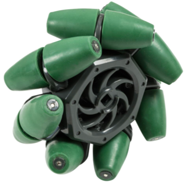
The cart has mecanum wheels, which give it the freedom to roll forward, backward, left, right, and on any floor diagonal, as well as rotate about it’s center. The movement of the cart is a function of the wheel radius (R), wheel separation width (W), and the wheel separation length (L).
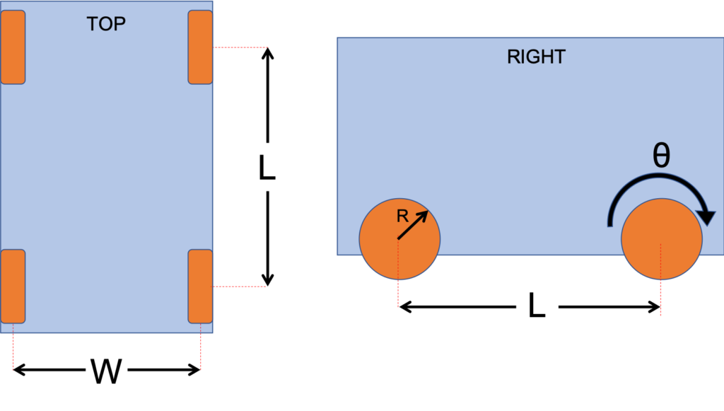
The left and right wheels are mounted as mirrors of each other, so the condition where the left and right wheels are spinning in the same direction is defined as $\omega_{right}=-\omega_{left}$. As you’d expect, each wheel of the cart has the same radius.
$\omega=\theta/ t$ where $\omega$ is the angular velocity of the wheel (rad/s), $\theta$ is it’s angular displacement (radians), and $t$ is the elapsed time (seconds).
W=2 meters
R=2.54E-01 meters
L=.3125 meters
Driving Forward
To drive forward, the cart needs:
$$\omega_{FL}=\omega_{RL}=-\omega_{FR}=-\omega_{RR}$$
Where FL denotes Front Left wheel, FR denotes Front Right wheel, RL denotes Rear Left wheel, and RR denotes Rear Right wheel. Since the angular velocity of each wheel is the same, the forward velocity of the cart (when driving straight) is the same as the velocity of a wheel rolling without slipping:
$$v_{cart}=\omega*R$$
Driving in reverse is simply the negative of driving forward:
$$-\omega_{FL}=-\omega_{RL}=\omega_{FR}=\omega_{RR}$$
Driving Sideways
For the purposes of this project, we preferred driving in forward/reverse, but the cart is equally capable of horizontal movement.
$$v_{cart_{horizontal}}=\frac{R}{4}(-\omega_{FL}+\omega_{FR}+\omega_{RL}-\omega_{RL})$$
Rotation About Cart Center
One of the most useful aspects of the mecanum wheels is their ability to rotate the cart about its center with a zero turning radius.
$$\omega_{cart}=\frac{R}{4(W+L)}(-\omega_{FL}+\omega_{FR}+\omega_{RL}-\omega_{RR})$$
This is the angular velocity of the cart. To rotate the cart a specific amount, we need to include time.
$$t=\frac{\omega_{cart}}{\theta}$$
$\theta$ is in radians.
Cart Path Planning
Note that the distances expressed in this section are different than the distances in the DH table. Floor tiles are 2×2$m^2$. The code takes floor tiles as its input desired distance and then converts that to meters.
- Drive forward $d_1=23m$
- Rotate $90°$
- Drive forward $d_2=38m$
- Rotate $-90°$
- Drive forward $23m$
- Rotate $-90°$
- Drive forward $d_4=31m$
- Rotate $90°$
- Drive backwards $d_5=6m$
- Use the arm to grab the object
- Drive forward $d_5=6m$
- Rotate $90°$
- Drive forward $d_4=31m$
- Rotate $90°$
- Drive forward $d_6=48m$
- Use the arm to place the object
- Rotate $90°$
- Drive forward $d_2=39m$
Inverse Kinematics
The 7 degrees of freedom of the manipulator make solving the Inverse Kinematics with either geometric or algebraic approaches extraordinarily challenging. Sometimes we can lock joints to simplify the problem and make it more easily approachable, but we didn’t want to sacrifice the robot’s functionality. Instead, we use MATLAB’s inverse kinematic solver tool with a RigidBodyTree robot model to solve the Inverse Kinematics. We specify each pose of the robot for each step of it’s task(s) and use those as inputs for MATLAB. The pose calculation is the same as the set of equations used in the Forward Kinematics section to produce the A matrices. This is the transform from the manipulator base frame to the object frame. If an additional set of transforms were needed, these equations could be reused and then multiplied together, just like before.
$$Rot_{z}=\begin{bmatrix} cos(\theta) & -sin(\theta) & 0 & 0\\ sin(\theta) & cos(\theta) & 0 & 0\\ 0 & 0 & 1 & 0\\ 0 & 0 & 0 & 1 \end{bmatrix}$$ $$Trans_{z}=\begin{bmatrix} 0 & 0 & 0 & 0\\ 0 & 0 & 0 & 0\\ 0 & 0 & 1 & d\\ 0 & 0 & 0 & 1 \end{bmatrix}$$ $$Trans_{x}=\begin{bmatrix} 0 & 0 & 0 & a\\ 0 & 0 & 0 & 0\\ 0 & 0 & 1 & 0\\ 0 & 0 & 0 & 1 \end{bmatrix}$$ $$Rot_{x}=\begin{bmatrix} 1 & 0 & 0 & 0\\ 0 & cos(\theta) & -sin(\theta) & 0\\ 0 & sin(\theta) & cos(\theta) & 0 \\ 0 & 0 & 0 & 1 \end{bmatrix}$$ $$A_{obj}=Rot_{z} Trans_{z} Trans_{x} Rot_{x}$$Dealing with Infinite Solutions
The manipulator arm has 7 degrees of freedom, and only 6 degrees are required to fully define a position (x,y,z) and orientation (pitch, roll, yaw) in 3D space. The robot is therefore capable of infinite solutions for the inverse kinematics for most of its work space. This extra freedom can cause issues. When the robot end effector is asked to move a very short distance, there is high chance the inverse kinematic solver will generate a valid solution that has several joints in drastically different positions.
The solution to this is actually fairly simple. The MATLAB Inverse Kinematic solver takes a starting guess as an input. The way we wrote it, the first time the program runs it takes the robot’s Home Configuration as the starting guess. It then saves the solved configuration and uses that as the starting guess input for the next subsequent solve. This can be seen in the code snip-it below. (Note that this is a partial excerpt of Simulation 4, reproduced here for clarity, but is incomplete and will not run as shown).
kuka=importrobot('iiwa14.urdf');
ik = robotics.InverseKinematics('RigidBodyTree',kuka);
LastConfig = homeConfiguration(kuka);
ik.SolverParameters.MaxIterations=1500;
function movearm=movearm(pose)
     disp('Attempting to solve Inverse Kinematics for that pose…');
     weights = [10 10 10 10 10 10];
     initialguess = LastConfig;
     [LastConfig,solnInfo] = ik('iiwa_link_7',pose,weights,initialguess)
     disp("Done solving inverse kinematics; Ready to move!");
 end
Let’s go through this line by line.
- Import the built in Kuka lbr iiwa 14 urdf file from MATLAB
- Set up that model with the inverse kinematic solver
- Set a variable called LastCofig equal to the Home Configuration of the Kuka arm. This will later represent the more recent arm configuration.
- MATLAB allows us to change the number of attempts it makes at solving the inverse kinematics. We leave it at the default (1500), but it can be easily changed if we need the solver to try harder.
- The movearm function, which takes in a pose, solves the inverse kinematics, and then actuates the arm
- Update the user about what’s happening
- Weight for pose tolerances, specified as a six-element vector. The first three elements correspond to the weights on the error in orientation for the desired pose. The last three elements correspond to the weights on the error in $xyz$ position for the desired pose. We kept them all equal.
- Create a new variable called initialguess and set it equal to LastConfig (currently the Home Configuration)
- Solve the inverse kinematics. Return LastConfig as the output. The next time movearm is called, LastConfig will refer to the current configuration of the arm.
Velocity Kinematics
We’ll be using the Jacobian for the velocity kinematics. $$J_v=[J_{v1} | J_{v2} | …|J_{vn}]$$ $$J_\omega=[J_{\omega1} | J_{\omega2} |…| J_{\omega n}]$$ \[J_{vi}= \begin{cases} z_{i-1} \times (o_n-o_{i-1}) &\text{ for revolute joint i}\\ z_{i-1} &\text{ for prismatic joint i} \end{cases} \] \[J_{\omega i}= \begin{cases} z_{i-1} &\text{ for revolute joint i}\\ 0 &\text{for prismatic joint i} \end{cases} \] The robot consists exclusively of revolute joints, so: $$J_{vi}= z_{i-1} \times (o_n-o_{i-1}) \text{ for i=1,2,…,7}$$ $$J_{\omega i}= z_{i-1} \text{ for i=1,2,…,7}$$ Please see the Appendix for the MATLAB code used to evaluate all of the Jacobians. Each $o_{i-1}$ term stems from the $A_1A_2…A_{i-1}$ matrix. It is the first 3 elements of the last column of that matrix. $z_{i-1}$ is the first 3 elements of the 3rd column of that matrix. $$o_0=\begin{bmatrix} 0\\0\\0 \end{bmatrix}$$ $$z_0=\begin{bmatrix} 0\\0\\1 \end{bmatrix}$$ $$o_1=\begin{bmatrix} 0\\0\\d_1 \end{bmatrix}$$ $$z_1=\begin{bmatrix} cos(\theta_1)\\sin(\theta_1)\\0 \end{bmatrix}$$ $$o_2=\begin{bmatrix} d_2*cos(\theta_1)\\d_2*sin(\theta_1)\\d1 \end{bmatrix}$$ $$z_2=\begin{bmatrix} sin(\theta_1)*sin(\theta_2)\\-cos(\theta_1)*sin(\theta_2)\\cos(\theta_2) \end{bmatrix}$$ $$o_3=\begin{bmatrix} d_2cos(\theta_1)+d_3sin(\theta_1)*sin(\theta_2)\\ d_2cos(\theta_1)-d_3cos(\theta_1)*sin(\theta_2)\\ d_1+d_3cos(\theta_2) \end{bmatrix}$$ $$z_3=\begin{bmatrix} cos(\theta_2)sin(\theta_1)sin(\theta_3)-cos(\theta_1)*cos(\theta_2)\\ -cos(\theta_3)sin(\theta_1)-cos(\theta_1)cos(\theta_2)sin(\theta_3)\\ -sin(\theta_2)sin(\theta_3) \end{bmatrix}$$ $$o_4=\begin{bmatrix} d_2cos(\theta_1)-d_4(cos(\theta_1)cos(\theta_3) – cos(\theta_2)sin(\theta_1)sin(\theta_3))+d_3sin(\theta_1)*sin(\theta_2)\\ d_2sin(\theta_1)-d_4(cos(\theta_3)sin(\theta_1) + cos(\theta_1)cos(\theta_2)sin(\theta_3))-d_2cos(\theta_1)-d_3cos(\theta_1)*sin(\theta_2)\\ d_1+d_3cos(\theta_2)-d_4*sin(\theta_2)sin(\theta_3) \end{bmatrix}$$ $$z4 =\begin{bmatrix} cos(\theta_4)sin(\theta_1)sin(\theta_2) – sin(\theta_4)(cos(\theta_1)sin(\theta_3) + cos(\theta_2)cos(\theta_3)sin(\theta_1))\\ -sin(\theta_4)(sin(\theta_1)sin(\theta_3) – cos(\theta_1)cos(\theta_2)cos(\theta_3)) – cos(\theta_1)cos(\theta_4)sin(\theta_2)\\ cos(\theta_2)cos(\theta_4) + cos(\theta_3)sin(\theta_2)sin(\theta_4)\end{bmatrix}$$ The remaining terms are too long to fit on this page, and are therefore omitted.Lagrangian Dynamics
We found a paper that experimentally determined the location of center of masses and inertia tensor matrices for each link of the Kuka arm.
V-Rep Simulation
See Section A.4 for the Matlab code used for this section. Fortunately, V-Rep comes with digital manipulable models of the Kuka lbr iiwa and mobile cart, so those did not have to be re-CADed.
The original version of the code was written entirely in Matlab, interacting with V-Rep through their Remote API. However, as testing progressed, it was found that this remote API interface was laggy and lacked crucial repeatability. Since timing (crucial for driving straight and turning) were hard coded into Matlab, any deviation in V-Rep’s processing ability caused irreparable harm to the simulation running. The simulation was susceptible to computer lag, and the presence of additional applications open could cause the simulation timing to change enough to ruin any trial. On numerous occasions, a perfect trial of maze navigation was run, and then found irreproducible while the screen was recorded using QuickTime. The deviation in timing caused by the additional program would cause the cart to turn too early or too late, stop moving too early or too late, or turn too much or too little. V-Rep’s built in tools for increasing simulation speed were also nonfunctional.
To combat this, most of the program functionality was re-written inside V-Rep’s scripting editor. This presented a new issue; the manipulator inverse kinematic solver was based on MATLAB’s Inverse Kinematic solving engine, and therefore not easily transferable to V-Rep. V-Rep could control the cart, but was unable to control the arm. The aforementioned lag and lack of repeatabilty precluded the incorporation of MATLAB code working in conjunction with the V-Rep script. While less practical than a single cohesive solution, it became clear that the only implentable solution was a five part piece-wise simulation: A pure V-Rep simulation would navigate the cart from the start to the object (Section A.4.1). A second simulation (starting at that point) would be controlled by MATLAB, and navigate the cart the remaining distance, operate the arm to retrieve the object, and then drive the cart away (Section A.4.2). The third simulation, starting from that point, would be pure V-Rep, and navigate the cart from that spot to the goal (Section A.4.1). MATLAB resumes control over the fourth simulation, starting from that point (SectionA.4.3). It would move the cart closer to the goal, reposition the arm, drop the object, and drive away. V-Rep would finish the course with a fifth simulation that drives the cart the remaining distance back to the start point (Section A.4.1). There wasn’t a practical way to string these discrete simulations into a continuous program, so they were run separately and the animations from each were later combined as videos. You can view a video of this combined simulation here:
This video is speed up 4x to make it easier to watch. If you’re paying close attention, you may notice some apparent discontinuities in the video. When the robot first approaches the table, it turns the front of the cart towards the table. In the next cut, the rear of the robot is approaching the table. This is due to a glitch in V-Rep that caused issues with the robot driving backwards after getting to the table. Attempting to drive the robot backwards in that particular spot would stall the program, so the robot was manually reversed for the second shot. Right around the 14 second mark, you’ll see the cart drive away on a diagonal. This demonstrates the unreliability of the simulation – other trials (not recorded) made that turn at 90 degrees. The 3rd simulation clip starts with the robot straight, which is why it continues on the proper trajectory at the next cut.
Gripping in V-Rep
Many of the available grippers that come with V-Rep have warnings attached. Realistic gripping in V-Rep, they warn, is very difficult to do correctly. It requires tremendous precision with placement, orientation, and gripper forces, which can take significant time to fine-tune. Especially with the poor repeatablity found in V-Rep, this style of gripping seemed particularly infeasible. The warning labels offered a solution – artificial gripping. This technique does not involve any gripper mechanics at all, preferring instead to script the mating of an object to the gripper coordinate system. Once the object was made a child of the ‘parent’ gripper, it’s position and orientation would match the gripper and move accordingly. This technique, while effective for demonstration purposes, is not a realistic or practical way to grip objects, and has some shortcomings. The “grabbed” object becomes attached to the gripper frame, regardless of the distance between the two. This does not move the object or align it with the gripper in any way. If the gripper is not close to the object when it “grabs”, the object will be seen floating as if attached to a long invisible pole affixed to the gripper.
References
- [1] K. AG, “KUKA LMR iiwa,” 2017. [Online]. Available: https://www.kuka.com/en-us/products/mobility/ mobile-robot-systems/kmr-iiwa
- [2] K. Roboter, “NEW: transport platform by KUKA Roboter,” 2019. [Online]. Available: https: //trends.directindustry.com/kuka-ag/project-17587-122708.html
- [3] C. Kessens, “Lecture 1: Introduction to Robot Modeling,” Sept 2019.
- [4] M. Spong, S. Hutchinson, and M. Vidyasagar, Robot Modeling and Control. Wiley, 2005.
- [5] C. Kessens, “Lecture 3: Forward Kinematics,” Sept 2019.
- [6] R. for Roboticists, “Drive kinematics: Skid steer and mecanum (ROS twist included),” 2016. [Online]. Available: https://robohub.org/drive-kinematics-skid-steer-and-mecanum-ros-twist-included/
- [7] MATLAB, “inversekinematics — create inverse kinematic solver.” [Online]. Available: https://www.mathworks. com/help/robotics/ref/inversekinematics-system-object.html
- [8] C. Kessens, “Lecture 5: Jacobian and Singularities,” Sept 2019.
- [9] Y. R. Stürz, L. M. Affolter, and R. S. Smith, “Parameter identification of the kuka lbr iiwa robot including constraints on physical feasibility,” IFAC-PapersOnLine, vol. 50, no. 1, pp. 6863 – 6868, 2017, 20th IFAC World Congress. [Online]. Available: http://www.sciencedirect.com/science/article/pii/S2405896317317147
- [10] C. Kessens, “Lecture 9: Dynamics II,” Nov 2019.
- [11] N. K., “05: Matlab Robot Simulation with V-REP – Part 1,” Dec 2016. [Online]. Available: https://www.youtube.com/watch?v=piI5wYEXUms
- [12] ——, “05: Matlab Robot Simulation with V-REP – Part 2,” Dec 2016. [Online]. Available: https://www.youtube.com/watch?v=mal48Vd-DQY
Bloopers
A collection of mishaps, mistakes, errors, and glitches produced in the trial and error of learning to use V-Rep correctly. Please enjoy (sound on):
Appendix
You can download the files related to this project from here:
https://github.com/BrianBock/KUKA_KMR
A. Matlab Code
A.1 MATLAB Code for DH Table and A Matrices
clearvars
syms t1 t2 t3 t4 d1 d2 d3 d4 t5 d5 t6 d6 d7 t7

%%%%%% A1 %%%%%%%%%
Rotz1=[cos(t1)*cosd(90)-sin(t1)*sind(90) -(sin(t1)*cosd(90)+cos(t1)*sind(90)) 0 0;
       (sin(t1)*cosd(90)+cos(t1)*sind(90)) cos(t1)*cosd(90)-sin(t1)*sind(90) 0 0;
       0 0 1 0;
       0 0 0 1];

Transz1=[1 0 0 0;
         0 1 0 0;
         0 0 1 d1;
         0 0 0 1];

Transx1=eye(4);

Rotx1=[1 0 0 0;
       0 cosd(90) -sind(90) 0;
       0 sind(90) cosd(90) 0
       0 0 0 1];


A1=Rotz1*Transz1*Transx1*Rotx1

%%%%%% A2 %%%%%%%%%

Rotz2=[cos(t2) -sin(t2) 0 0;
       sin(t2) cos(t2) 0 0;
       0 0 1 0;
       0 0 0 1];

Transz2=[1 0 0 0;
         0 1 0 0;
         0 0 1 d2;
         0 0 0 1];

Transx2=eye(4);

Rotx2=[1 0 0 0;
       0 cosd(-90) -sind(-90) 0;
       0 sind(-90) cosd(-90) 0
       0 0 0 1];


A2=Rotz2*Transz2*Transx2*Rotx2

%%%%%% A3 %%%%%%%%%

Rotz3=[cos(t3) -sin(t3) 0 0;
       sin(t3) cos(t3) 0 0;
       0 0 1 0;
       0 0 0 1];

Transz3=[1 0 0 0;
         0 1 0 0;
         0 0 1 d3;
         0 0 0 1];

Transx3=eye(4);

Rotx3=[1 0 0 0;
       0 cosd(-90) -sind(-90) 0;
       0 sind(-90) cosd(-90) 0
       0 0 0 1];


A3=Rotz3*Transz3*Transx3*Rotx3


%%%%%% A4 %%%%%%%%%

Rotz4=[cos(t4) -sin(t4) 0 0;
       sin(t4) cos(t4) 0 0;
       0 0 1 0;
       0 0 0 1];

Transz4=[1 0 0 0;
         0 1 0 0;
         0 0 1 d4;
         0 0 0 1];

Transx4=eye(4);

Rotx4=[1 0 0 0;
       0 cosd(90) -sind(90) 0;
       0 sind(90) cosd(90) 0
       0 0 0 1];


A4=Rotz4*Transz4*Transx4*Rotx4


%%%%%% A5 %%%%%%%%%

Rotz5=[cos(t5) -sin(t5) 0 0;
       sin(t5) cos(t5) 0 0;
       0 0 1 0;
       0 0 0 1];

Transz5=[1 0 0 0;
         0 1 0 0;
         0 0 1 d5;
         0 0 0 1];

Transx5=eye(4);

Rotx5=[1 0 0 0;
       0 cosd(90) -sind(90) 0;
       0 sind(90) cosd(90) 0
       0 0 0 1];


A5=Rotz5*Transz5*Transx5*Rotx5


%%%%%% A6 %%%%%%%%%

Rotz6=[cos(t6) -sin(t6) 0 0;
       sin(t6) cos(t6) 0 0;
       0 0 1 0;
       0 0 0 1];

Transz6=[1 0 0 0;
         0 1 0 0;
         0 0 1 d6;
         0 0 0 1];

Transx6=eye(4);

Rotx6=[1 0 0 0;
       0 cosd(-90) -sind(-90) 0;
       0 sind(-90) cosd(-90) 0
       0 0 0 1];


A6=Rotz6*Transz6*Transx6*Rotx6


%%%%%% A7 %%%%%%%%%

Rotz7=[cos(t7)*cosd(-90)-sin(t7)*sind(-90) -(sin(t7)*cosd(-90)+cos(t7)*sind(-90)) 0 0;
      (sin(t7)*cosd(-90)+cos(t7)*sind(-90)) cos(t7)*cosd(-90)-sin(t7)*sind(-90) 0 0;
       0 0 1 0;
       0 0 0 1];

Transz7=[1 0 0 0;
         0 1 0 0;
         0 0 1 d7;
         0 0 0 1];

Transx7=eye(4);

Rotx7=eye(4);


A7=Rotz7*Transz7*Transx7*Rotx7


T=A1*A2*A3*A4*A5*A6*A7
A.2 MATLAB Code for Jacobian
This section immediately follows the A Matrices code and has access to the same saved variables.
%% Jacobian

o0=[0;0;0]
z0=[0;0;1]

o1=A1(1:3,4)
z1=A1(1:3,3)

A1A2=A1*A2;

o2=A1A2(1:3,4)
z2=A1A2(1:3,3)

A1A2A3=A1*A2*A3;
o3=A1A2A3(1:3,4)
z3=A1A2A3(1:3,3)

A1A2A3A4=A1*A2*A3*A4;
o4=A1A2A3A4(1:3,4)
z4=A1A2A3A4(1:3,3)

A1A2A3A4A5=A1*A2*A3*A4*A5;
o5=A1A2A3A4A5(1:3,4)
z5=A1A2A3A4A5(1:3,3)

A1A2A3A4A5A6=A1*A2*A3*A4*A5*A6;
o6=A1A2A3A4A5A6(1:3,4)
z6=A1A2A3A4A5A6(1:3,3)

A1A2A3A4A5A6A7=A1*A2*A3*A4*A5*A6*A7;
o7=A1A2A3A4A5A6A7(1:3,4)
z7=A1A2A3A4A5A6A7(1:3,3)

Jacobian=[cross(z0,(o7-o0)) cross(z1,(o7-o1)) cross(z2,(o7-o2)) cross(z3,(o7-o3))   cross(z4,(o7-o4)) cross(z5,(o7-o5)) cross(z6,(o7-o6));
z0.*z0 z1.*z0 z2.*z0 z3.*z0 z4.*z0 z5.*z0 z6.*z0]
A.3 MATLAB Code to Check Jacobian
%% Joint 1
clearvars
syms t1 t2 t3 t4 d1 d2 d3 d4 t5 d5 t6 d6 d7 t7
t1=0;
t2=0;
t3=0;
t4=0;
t5=0;
t6=0;
t7=0;

d1=0;
d2=0;
d3=.42;
d4=0;
d5=.4;
d6=0;
d7=0;

%%%%%% A1 %%%%%%%%%
Rotz1=[cos(t1+pi/2) -sin(t1+pi/2) 0 0;
       sin(t1+pi/2) cos(t1+pi/2) 0 0;
       0 0 1 0;
       0 0 0 1];

Transz1=[1 0 0 0;
         0 1 0 0;
         0 0 1 d1;
         0 0 0 1];

Transx1=eye(4);

Rotx1=[1 0 0 0;
       0 cosd(90) -sind(90) 0;
       0 sind(90) cosd(90) 0
       0 0 0 1];


A1=Rotz1*Transz1*Transx1*Rotx1

%%%%%% A2 %%%%%%%%%

Rotz2=[cos(t2) -sin(t2) 0 0;
       sin(t2) cos(t2) 0 0;
       0 0 1 0;
       0 0 0 1];

Transz2=[1 0 0 0;
         0 1 0 0;
         0 0 1 d2;
         0 0 0 1];

Transx2=eye(4);

Rotx2=[1 0 0 0;
       0 cosd(-90) -sind(-90) 0;
       0 sind(-90) cosd(-90) 0
       0 0 0 1];


A2=Rotz2*Transz2*Transx2*Rotx2

%%%%%% A3 %%%%%%%%%

Rotz3=[cos(t3) -sin(t3) 0 0;
       sin(t3) cos(t3) 0 0;
       0 0 1 0;
       0 0 0 1];

Transz3=[1 0 0 0;
         0 1 0 0;
         0 0 1 d3;
         0 0 0 1];

Transx3=eye(4);

Rotx3=[1 0 0 0;
       0 cosd(-90) -sind(-90) 0;
       0 sind(-90) cosd(-90) 0
       0 0 0 1];


A3=Rotz3*Transz3*Transx3*Rotx3


%%%%%% A4 %%%%%%%%%

Rotz4=[cos(t4) -sin(t4) 0 0;
       sin(t4) cos(t4) 0 0;
       0 0 1 0;
       0 0 0 1];

Transz4=[1 0 0 0;
         0 1 0 0;
         0 0 1 d4;
         0 0 0 1];

Transx4=eye(4);

Rotx4=[1 0 0 0;
       0 cosd(90) -sind(90) 0;
       0 sind(90) cosd(90) 0
       0 0 0 1];


A4=Rotz4*Transz4*Transx4*Rotx4


%%%%%% A5 %%%%%%%%%

Rotz5=[cos(t5) -sin(t5) 0 0;
       sin(t5) cos(t5) 0 0;
       0 0 1 0;
       0 0 0 1];

Transz5=[1 0 0 0;
         0 1 0 0;
         0 0 1 d5;
         0 0 0 1];

Transx5=eye(4);

Rotx5=[1 0 0 0;
       0 cosd(90) -sind(90) 0;
       0 sind(90) cosd(90) 0
       0 0 0 1];


A5=Rotz5*Transz5*Transx5*Rotx5


%%%%%% A6 %%%%%%%%%

Rotz6=[cos(t6) -sin(t6) 0 0;
       sin(t6) cos(t6) 0 0;
       0 0 1 0;
       0 0 0 1];

Transz6=[1 0 0 0;
         0 1 0 0;
         0 0 1 d6;
         0 0 0 1];

Transx6=eye(4);

Rotx6=[1 0 0 0;
       0 cosd(-90) -sind(-90) 0;
       0 sind(-90) cosd(-90) 0
       0 0 0 1];


A6=Rotz6*Transz6*Transx6*Rotx6


%%%%%% A7 %%%%%%%%%

Rotz7=[cos(t7-pi/2) -sin(t7-pi/2) 0 0;
       sin(t7-pi/2) cos(t7-pi/2) 0 0;
       0 0 1 0;
       0 0 0 1];

Transz7=[1 0 0 0;
         0 1 0 0;
         0 0 1 d7;
         0 0 0 1];

Transx7=eye(4);

Rotx7=eye(4);


A7=Rotz7*Transz7*Transx7*Rotx7


T=A1*A2*A3*A4*A5*A6*A7

%% Jacobian

o0=[0;0;0]
z0=[0;0;1]

o1=A1(1:3,4)
z1=A1(1:3,3)

A1A2=A1*A2;
o2=A1A2(1:3,4)
z2=A1A2(1:3,3)

A1A2A3=A1*A2*A3;
o3=A1A2A3(1:3,4)
z3=A1A2A3(1:3,3)

A1A2A3A4=A1*A2*A3*A4;
o4=A1A2A3A4(1:3,4)
z4=A1A2A3A4(1:3,3)

A1A2A3A4A5=A1*A2*A3*A4*A5;
o5=A1A2A3A4A5(1:3,4)
z5=A1A2A3A4A5(1:3,3)

A1A2A3A4A5A6=A1*A2*A3*A4*A5*A6;
o6=A1A2A3A4A5A6(1:3,4)
z6=A1A2A3A4A5A6(1:3,3)

A1A2A3A4A5A6A7=A1*A2*A3*A4*A5*A6*A7;
o7=A1A2A3A4A5A6A7(1:3,4)
z7=A1A2A3A4A5A6A7(1:3,3)


Jv=[cross(z0,(o7-o0)) cross(z1,(o7-o1)) cross(z2,(o7-o2))...
    cross(z3,(o7-o3)) cross(z4,(o7-o4)) cross(z5,(o7-o5)) ...
    cross(z6,(o7-o6))]
Jw=[z0 z1 z2 z3 z4 z5 z6]
A.4 MATLAB & V-REP Simulation Code
Two tutorials in particular [11], [12], were fundamental to the creation of functioning code for this section. One quick comment on notation: the “- -” symbol (2 dashes, no space) in V-REP denotes an in-line comment, but the syntax highlighting package used here is built for MATLAB syntax and only recognizes “\%” as a comment. For accurate comment coloring below, a “\%” was added at the start of each comment after each double dash.
A.4.1 Simulation 1,3,5: V-Rep
Navigate cart to the object and then to goal.
function sysCall_threadmain()
    h={-1,-1,-1}
    h[1]=sim.getObjectHandle('Omnirob_FLwheel_motor')
    h[2]=sim.getObjectHandle('Omnirob_FRwheel_motor')
    h[3]=sim.getObjectHandle('Omnirob_RRwheel_motor')
    h[4]=sim.getObjectHandle('Omnirob_RLwheel_motor')
    v1=9.842519685  --%rad/s

    --%Go to the item
    drive(11.5,1)
    rotate(math.pi/2)
    drive(19.5,1)
    rotate(-math.pi/2)
    drive(11.5,1)
    rotate(-math.pi/2)
    drive(15.5,1)
    rotate(-math.pi/2)
    drive(3,1) --%at the object

    rotate(math.pi/2)
    rotate(math.pi/2)

    drive(3,1)
    rotate(math.pi/2)
    drive(15.5,1)
    rotate(math.pi/2)
    drive(24,1)
    rotate(1.1*math.pi/2)
    drive(19.5,1)
    rotate(math.pi/2)
    --%drive(11.5,-1)
end


function drive(distance,direction)--%distance is in floor tiles
    -- %Drive Forward --
    distance=distance*2 --%floor tiles are 2m^2;
    wheel_radius=2.5400E-01; --%meters
    t=distance/(v1*wheel_radius)
    v1=direction*v1
    sim.setJointTargetVelocity(h[1],v1)
    sim.setJointTargetVelocity(h[2],-v1)
    sim.setJointTargetVelocity(h[3],-v1)
    sim.setJointTargetVelocity(h[4],v1)
    sim.wait(t)
    sim.setJointTargetVelocity(h[1],0)
    sim.setJointTargetVelocity(h[2],0)
    sim.setJointTargetVelocity(h[3],0)
    sim.setJointTargetVelocity(h[4],0)
    sim.wait(1)
end

function rotate(angle)
    wheel_separation_width=2;--%meters
    wheel_radius=2.5400E-01; --%meters
    wheel_separatation_length=.625/2; --%meters

    v_wheel_front_left = -(1/wheel_radius)*((wheel_separation_width + wheel_separatation_length)*angle)
    v_wheel_front_right = -(1/wheel_radius)*((wheel_separation_width + wheel_separatation_length)*angle)
    v_wheel_rear_left = -(1/wheel_radius)*((wheel_separation_width + wheel_separatation_length)*angle)
    v_wheel_rear_right = -(1/wheel_radius)*((wheel_separation_width + wheel_separatation_length)*angle)

    --%spin wheels
    sim.setJointTargetVelocity(h[1],v_wheel_front_left);
    sim.setJointTargetVelocity(h[2],v_wheel_front_right);
    sim.setJointTargetVelocity(h[3],v_wheel_rear_left);
    sim.setJointTargetVelocity(h[4],v_wheel_rear_right);
    sim.wait(1.18)
    --%stop wheels
    sim.setJointTargetVelocity(h[1],0);
    sim.setJointTargetVelocity(h[2],0);
    sim.setJointTargetVelocity(h[3],0);
    sim.setJointTargetVelocity(h[4],0);
    sim.wait(1);


end
A.4.2 Simulation 2: MATLAB
Move the cart closer to the object. Manipulate the arm to retrive the object. Drive away.
%% Project Setup
clc
clear all
global vrep;
global clientID;
global wheel_separation_width;
global wheel_radius;
global wheel_separatation_length;
global KMR_Front_Right_Wheel;
global KMR_Front_Left_Wheel;
global KMR_Rear_Right_Wheel;
global KMR_Rear_Left_Wheel;
global KUKA_Joint1;
global KUKA_Joint2;
global KUKA_Joint3;
global KUKA_Joint4;
global KUKA_Joint5;
global KUKA_Joint6;
global KUKA_Joint7;
global ik;
global kuka;
global LastConfig;
global gripper;
global gripper_connect;

wheel_separation_width=.5/2;%m
wheel_radius=2.5400E-01; %meters
wheel_separatation_length=.625/2; %m


kuka=importrobot("iiwa14.urdf");
ik = robotics.InverseKinematics('RigidBodyTree',kuka);
initialguess = homeConfiguration(kuka);
LastConfig=initialguess;
ik.SolverParameters.MaxIterations=1500;
%% Connect to VRep

vrep=remApi('remoteApi'); % using the prototype file (remoteApiProto.m)
vrep.simxFinish(-1); % just in case, close all opened connections

clientID=vrep.simxStart('127.0.0.1',19999,true,true,5000,5);


if (clientID<=-1) % If not true, we've connected
    disp('Cannot connect to VRep. Make sure the Vrep simulation is already running');
    return;
end

if(clientID>-1)
disp('Connected to vrep. Ready to go!');
end

%% Get Object Handles for all Parts

[~, KMR_Front_Right_Wheel]=vrep.simxGetObjectHandle(clientID, 'Omnirob_FRwheel_motor', vrep.simx_opmode_blocking);
[~, KMR_Front_Left_Wheel]=vrep.simxGetObjectHandle(clientID, 'Omnirob_FLwheel_motor', vrep.simx_opmode_blocking);
[~, KMR_Rear_Right_Wheel]=vrep.simxGetObjectHandle(clientID, 'Omnirob_RRwheel_motor', vrep.simx_opmode_blocking);
[~, KMR_Rear_Left_Wheel]=vrep.simxGetObjectHandle(clientID, 'Omnirob_RLwheel_motor', vrep.simx_opmode_blocking);
[~, KUKA_Joint1]=vrep.simxGetObjectHandle(clientID, 'LBR_iiwa_14_R820_joint1', vrep.simx_opmode_blocking);
[~, KUKA_Joint2]=vrep.simxGetObjectHandle(clientID, 'LBR_iiwa_14_R820_joint2', vrep.simx_opmode_blocking);
[~, KUKA_Joint3]=vrep.simxGetObjectHandle(clientID, 'LBR_iiwa_14_R820_joint3', vrep.simx_opmode_blocking);
[~, KUKA_Joint4]=vrep.simxGetObjectHandle(clientID, 'LBR_iiwa_14_R820_joint4', vrep.simx_opmode_blocking);
[~, KUKA_Joint5]=vrep.simxGetObjectHandle(clientID, 'LBR_iiwa_14_R820_joint5', vrep.simx_opmode_blocking);
[~, KUKA_Joint6]=vrep.simxGetObjectHandle(clientID, 'LBR_iiwa_14_R820_joint6', vrep.simx_opmode_blocking);
[~, KUKA_Joint7]=vrep.simxGetObjectHandle(clientID, 'LBR_iiwa_14_R820_joint7', vrep.simx_opmode_blocking);
[~, gripper]=vrep.simxGetObjectHandle(clientID, 'RG2_openCloseJoint', vrep.simx_opmode_blocking);
[~, gripper_connect]=vrep.simxGetObjectHandle(clientID, 'RG2_attachPoint', vrep.simx_opmode_blocking);
[~, item]=vrep.simxGetObjectHandle(clientID, 'Box', vrep.simx_opmode_blocking);


%% Drive the Cart
drive(5.7,-5);


%% Object Retrieval Pose

%The object to retrieve is a disc on a spindle. The spindle is a distance
%l_obj along the (manipulator) Xo axis, h_obj along the (manipulator) Zo
%axis. It is then rotated by theta_obj about the Z axis, and by alpha_obj
%about the X axis.

theta_obj=deg2rad(30);
h_obj=.25;
l_obj=-.75;
alpha_obj=deg2rad(210);


Rotz_obj=[cos(theta_obj) -sin(theta_obj)  0 0;
        sin(theta_obj) cos(theta_obj) 0 0;
       0 0 1 0;
       0 0 0 1];

Transz_obj=[1 0 0 0;
         0 1 0 0;
         0 0 1 h_obj;
         0 0 0 1];

Transx_obj=[1 0 0 l_obj;
            0 1 0 0;
            0 0 1 0;
            0 0 0 1];

Rotx_obj=[1 0 0 0;
       0 cos(alpha_obj) -sin(alpha_obj) 0;
       0 sin(alpha_obj) cos(alpha_obj) 0
       0 0 0 1];


A_obj=Rotz_obj*Transz_obj*Transx_obj*Rotx_obj;


movearm(A_obj)
pause(2)

grip(item,1);

%% Object Removal
%To remove the disc from the spindle, it must be slide a distance d_remove
%in the Z_obj direction

dz_remove=-.25;
dx_remove=0;

Rotz_remove=eye(4);

Transz_remove=[1 0 0 0;
               0 1 0 0;
               0 0 1 dz_remove;
               0 0 0 1];

Transx_remove=[1 0 0 dx_remove;
               0 1 0 0;
               0 0 1 0;
               0 0 0 1];

Rotx_remove=eye(4);
A_remove=Rotz_remove*Transz_remove*Transx_remove*Rotx_remove;

A_0_remove=A_obj*A_remove;

%show(kuka,A_0_remove)

movearm(A_0_remove)

%movearm(randomConfiguration(kuka));


drive(5,5)
rotate(120);
drive(5,5)


vrep.simxFinish(-1); % Close the connection


vrep.delete(); % Call the vrep destructor


%% Functions

function driver=drive(distance, speed)% Drive Forward (direction =1), Reverse (direction=-1)
global clientID;
global vrep;
global KMR_Front_Right_Wheel;
global KMR_Front_Left_Wheel;
global KMR_Rear_Right_Wheel;
global KMR_Rear_Left_Wheel;

if(speed>0)
    disp("Driving Foward!");
elseif(speed<0)
    disp("Beep beep beep - driving backwards!");
end
        wheel_velocity=speed;
        duration=abs(distance/(.3*speed));
        %spin wheels
        [~]=vrep.simxSetJointTargetVelocity(clientID,KMR_Front_Left_Wheel,...
        wheel_velocity,vrep.simx_opmode_blocking);
        [~]=vrep.simxSetJointTargetVelocity(clientID,KMR_Front_Right_Wheel,...
        -wheel_velocity,vrep.simx_opmode_blocking);
        [~]=vrep.simxSetJointTargetVelocity(clientID,KMR_Rear_Right_Wheel,...
        -wheel_velocity,vrep.simx_opmode_blocking);
        [~]=vrep.simxSetJointTargetVelocity(clientID,KMR_Rear_Left_Wheel,...
        wheel_velocity,vrep.simx_opmode_blocking);
        pause(duration)
        %stop wheels
        [~]=vrep.simxSetJointTargetVelocity(clientID,KMR_Front_Left_Wheel,0,vrep.simx_opmode_blocking);
        [~]=vrep.simxSetJointTargetVelocity(clientID,KMR_Front_Right_Wheel,0,vrep.simx_opmode_blocking);
        [~]=vrep.simxSetJointTargetVelocity(clientID,KMR_Rear_Left_Wheel,0,vrep.simx_opmode_blocking);
        [~]=vrep.simxSetJointTargetVelocity(clientID,KMR_Rear_Right_Wheel,0,vrep.simx_opmode_blocking);
        pause(.5);
end


function pivot=rotate(angle) % Rotate about central axis (deg)
    global clientID;
    global vrep;
    global KMR_Front_Right_Wheel;
    global KMR_Front_Left_Wheel;
    global KMR_Rear_Right_Wheel;
    global KMR_Rear_Left_Wheel;
    global wheel_radius;
    global wheel_separation_width
    global wheel_separatation_length
    angle=deg2rad(angle);

    disp("Turning!");
    % https://robohub.org/drive-kinematics-skid-steer-and-mecanum-ros-twist-included/
    v_wheel_front_left = -(1/wheel_radius)*((wheel_separation_width + wheel_separatation_length)*angle);
    v_wheel_front_right = -(1/wheel_radius)*((wheel_separation_width + wheel_separatation_length)*angle);
    v_wheel_rear_left = -(1/wheel_radius)*((wheel_separation_width + wheel_separatation_length)*angle);
    v_wheel_rear_right = -(1/wheel_radius)*((wheel_separation_width + wheel_separatation_length)*angle);

    %spin wheels
    [~]=vrep.simxSetJointTargetVelocity(clientID,KMR_Front_Left_Wheel,...
    v_wheel_front_left,vrep.simx_opmode_blocking);
    [~]=vrep.simxSetJointTargetVelocity(clientID,KMR_Front_Right_Wheel, v_wheel_front_right,vrep.simx_opmode_blocking);
    [~]=vrep.simxSetJointTargetVelocity(clientID,KMR_Rear_Right_Wheel,...
    v_wheel_rear_left,vrep.simx_opmode_blocking);
    [~]=vrep.simxSetJointTargetVelocity(clientID,KMR_Rear_Left_Wheel,...
    v_wheel_rear_right,vrep.simx_opmode_blocking);
    pause(1)
    %stop wheels
    [~]=vrep.simxSetJointTargetVelocity(clientID,KMR_Front_Left_Wheel,0,vrep.simx_opmode_blocking);
    [~]=vrep.simxSetJointTargetVelocity(clientID,KMR_Front_Right_Wheel,0,vrep.simx_opmode_blocking);
    [~]=vrep.simxSetJointTargetVelocity(clientID,KMR_Rear_Left_Wheel,0,vrep.simx_opmode_blocking);
    [~]=vrep.simxSetJointTargetVelocity(clientID,KMR_Rear_Right_Wheel,0,vrep.simx_opmode_blocking);
    pause(.5);
end


function movearm=movearm(pose)
    global vrep;
    global kuka;
    global ik;
    global clientID;
    global KUKA_Joint1;
    global KUKA_Joint2;
    global KUKA_Joint3;
    global KUKA_Joint4;
    global KUKA_Joint5;
    global KUKA_Joint6;
    global KUKA_Joint7;
    global LastConfig;
    disp("Attempting to solve Inverse Kinematics for that pose...");
    weights = [10 10 10 10 10 10];
    initialguess = LastConfig;
    [LastConfig,solnInfo] = ik('iiwa_link_7',pose,weights,initialguess)
    disp("Done solving inverse kinematics; Ready to move!");


    j1=LastConfig(1).JointPosition;
    j2=LastConfig(2).JointPosition;
    j3=LastConfig(3).JointPosition;
    j4=LastConfig(4).JointPosition;
    j5=LastConfig(5).JointPosition;
    j6=LastConfig(6).JointPosition;
    j7=LastConfig(7).JointPosition;

    disp("Moving robot arm");

    [~]=vrep.simxSetJointTargetPosition(clientID,KUKA_Joint1,j1,vrep.simx_opmode_blocking);
    [~]=vrep.simxSetJointTargetPosition(clientID,KUKA_Joint2,j2,vrep.simx_opmode_blocking);
    [~]=vrep.simxSetJointTargetPosition(clientID,KUKA_Joint3,j3,vrep.simx_opmode_blocking);
    [~]=vrep.simxSetJointTargetPosition(clientID,KUKA_Joint4,j4,vrep.simx_opmode_blocking);
    [~]=vrep.simxSetJointTargetPosition(clientID,KUKA_Joint5,j5,vrep.simx_opmode_blocking);
    [~]=vrep.simxSetJointTargetPosition(clientID,KUKA_Joint6,j6,vrep.simx_opmode_blocking);
    [~]=vrep.simxSetJointTargetPosition(clientID,KUKA_Joint7,j7,vrep.simx_opmode_blocking);

    disp("Done moving");
    show(kuka,LastConfig);
end


function grabber=grip(obj,grab) %obj is the item to grab (handle) and grab is 1 (Grab) or 0 (let go)
    global clientID
    global gripper_connect
    global vrep;
    motorVelocity=0.05; %-- m/s
    motorForce=20; %-- N
    item=obj;

    if(grab==1) %grab it!
        [~]=vrep.simxSetObjectParent(clientID,item,gripper_connect,true,vrep.simx_opmode_blocking)
        disp('Grabbing!');
    elseif(grab==0)  %let go
        [~]=vrep.simxSetObjectParent(clientID,item,-1,true,vrep.simx_opmode_blocking)
        disp('Dropping!');
    end

end
A.4.3 Simulation 4: MATLAB
Drive towards the table. Move the arm to the deposition orientation. Drop the object. Drive away.
%% Project Setup
clc
clear all
global vrep;
global clientID;
global wheel_separation_width;
global wheel_radius;
global wheel_separatation_length;
global KMR_Front_Right_Wheel;
global KMR_Front_Left_Wheel;
global KMR_Rear_Right_Wheel;
global KMR_Rear_Left_Wheel;
global KUKA_Joint1;
global KUKA_Joint2;
global KUKA_Joint3;
global KUKA_Joint4;
global KUKA_Joint5;
global KUKA_Joint6;
global KUKA_Joint7;
global ik;
global kuka;
global LastConfig;
global gripper;
global gripper_connect;

wheel_separation_width=.5/2;%m
wheel_radius=2.5400E-01; %meters
wheel_separatation_length=.625/2; %m


kuka=importrobot("iiwa14.urdf");
ik = robotics.InverseKinematics('RigidBodyTree',kuka);
initialguess = homeConfiguration(kuka);
LastConfig=initialguess;
ik.SolverParameters.MaxIterations=1500;
%% Connect to VRep

vrep=remApi('remoteApi'); % using the prototype file (remoteApiProto.m)
vrep.simxFinish(-1); % just in case, close all opened connections

clientID=vrep.simxStart('127.0.0.1',19999,true,true,5000,5);


if (clientID<=-1) % If not true, we've connected
    disp('Cannot connect to VRep. Make sure the Vrep simulation is already running');
    return;
end

if(clientID>-1)
disp('Connected to vrep. Ready to go!');
end

%% Get Object Handles for all Parts

[~, KMR_Front_Right_Wheel]=vrep.simxGetObjectHandle(clientID, 'Omnirob_FRwheel_motor', vrep.simx_opmode_blocking);
[~, KMR_Front_Left_Wheel]=vrep.simxGetObjectHandle(clientID, 'Omnirob_FLwheel_motor', vrep.simx_opmode_blocking);
[~, KMR_Rear_Right_Wheel]=vrep.simxGetObjectHandle(clientID, 'Omnirob_RRwheel_motor', vrep.simx_opmode_blocking);
[~, KMR_Rear_Left_Wheel]=vrep.simxGetObjectHandle(clientID, 'Omnirob_RLwheel_motor', vrep.simx_opmode_blocking);
[~, KUKA_Joint1]=vrep.simxGetObjectHandle(clientID, 'LBR_iiwa_14_R820_joint1', vrep.simx_opmode_blocking);
[~, KUKA_Joint2]=vrep.simxGetObjectHandle(clientID, 'LBR_iiwa_14_R820_joint2', vrep.simx_opmode_blocking);
[~, KUKA_Joint3]=vrep.simxGetObjectHandle(clientID, 'LBR_iiwa_14_R820_joint3', vrep.simx_opmode_blocking);
[~, KUKA_Joint4]=vrep.simxGetObjectHandle(clientID, 'LBR_iiwa_14_R820_joint4', vrep.simx_opmode_blocking);
[~, KUKA_Joint5]=vrep.simxGetObjectHandle(clientID, 'LBR_iiwa_14_R820_joint5', vrep.simx_opmode_blocking);
[~, KUKA_Joint6]=vrep.simxGetObjectHandle(clientID, 'LBR_iiwa_14_R820_joint6', vrep.simx_opmode_blocking);
[~, KUKA_Joint7]=vrep.simxGetObjectHandle(clientID, 'LBR_iiwa_14_R820_joint7', vrep.simx_opmode_blocking);
[~, gripper]=vrep.simxGetObjectHandle(clientID, 'RG2_openCloseJoint', vrep.simx_opmode_blocking);
[~, gripper_connect]=vrep.simxGetObjectHandle(clientID, 'RG2_attachPoint', vrep.simx_opmode_blocking);
[~, item]=vrep.simxGetObjectHandle(clientID, 'Box', vrep.simx_opmode_blocking);


%% Drive the Cart
drive(9,-5);


%% Object Deposition Pose
% The spindle is a distance %l_obj along the (manipulator) Xo axis, h_obj along the (manipulator) Zo
%axis. It is then rotated by theta_obj about the Z axis, and by alpha_obj
%about the X axis.

theta_obj=deg2rad(90);
h_obj=.4;
l_obj=.75;
alpha_obj=deg2rad(270);


Rotz_obj=[cos(theta_obj) -sin(theta_obj)  0 0;
        sin(theta_obj) cos(theta_obj) 0 0;
       0 0 1 0;
       0 0 0 1];

Transz_obj=[1 0 0 0;
         0 1 0 0;
         0 0 1 h_obj;
         0 0 0 1];

Transx_obj=[1 0 0 l_obj;
            0 1 0 0;
            0 0 1 0;
            0 0 0 1];

Rotx_obj=[1 0 0 0;
       0 cos(alpha_obj) -sin(alpha_obj) 0;
       0 sin(alpha_obj) cos(alpha_obj) 0
       0 0 0 1];


A_obj_1=Rotz_obj*Transz_obj*Transx_obj*Rotx_obj;


movearm(A_obj_1)
pause(2)

grip(item,0);

rotate(-100);
drive(5,5)

vrep.simxFinish(-1); % Close the connection


vrep.delete(); % Call the vrep destructor


%% Functions

function driver=drive(distance, speed)% Drive Forward (direction =1), Reverse (direction=-1)
global clientID;
global vrep;
global KMR_Front_Right_Wheel;
global KMR_Front_Left_Wheel;
global KMR_Rear_Right_Wheel;
global KMR_Rear_Left_Wheel;

if(speed>0)
    disp("Driving Foward!");
elseif(speed<0)
    disp("Beep beep beep - driving backwards!");
end
        wheel_velocity=speed;
        duration=abs(distance/(.3*speed));
        %spin wheels
        [~]=vrep.simxSetJointTargetVelocity(clientID,KMR_Front_Left_Wheel,...
    wheel_velocity,vrep.simx_opmode_blocking);
        [~]=vrep.simxSetJointTargetVelocity(clientID,KMR_Front_Right_Wheel,...
    -wheel_velocity,vrep.simx_opmode_blocking);
        [~]=vrep.simxSetJointTargetVelocity(clientID,KMR_Rear_Right_Wheel,...
    -wheel_velocity,vrep.simx_opmode_blocking);
        [~]=vrep.simxSetJointTargetVelocity(clientID,KMR_Rear_Left_Wheel,...
    wheel_velocity,vrep.simx_opmode_blocking);
        pause(duration)
        %stop wheels
        [~]=vrep.simxSetJointTargetVelocity(clientID,KMR_Front_Left_Wheel,0,...
    vrep.simx_opmode_blocking);
        [~]=vrep.simxSetJointTargetVelocity(clientID,KMR_Front_Right_Wheel,0,...
    vrep.simx_opmode_blocking);
        [~]=vrep.simxSetJointTargetVelocity(clientID,KMR_Rear_Left_Wheel,0,...
    vrep.simx_opmode_blocking);
        [~]=vrep.simxSetJointTargetVelocity(clientID,KMR_Rear_Right_Wheel,0,...
    vrep.simx_opmode_blocking);
        pause(.5);
end


function pivot=rotate(angle) % Rotate about central axis (deg)
    global clientID;
    global vrep;
    global KMR_Front_Right_Wheel;
    global KMR_Front_Left_Wheel;
    global KMR_Rear_Right_Wheel;
    global KMR_Rear_Left_Wheel;
    global wheel_radius;
    global wheel_separation_width
    global wheel_separatation_length
    angle=deg2rad(angle);

    disp("Turning!");
    % https://robohub.org/drive-kinematics-skid-steer-and-mecanum-ros-twist-included/
    v_wheel_front_left = -(1/wheel_radius)*((wheel_separation_width + wheel_separatation_length)*angle);
    v_wheel_front_right = -(1/wheel_radius)*((wheel_separation_width + wheel_separatation_length)*angle);
    v_wheel_rear_left = -(1/wheel_radius)*((wheel_separation_width + wheel_separatation_length)*angle);
    v_wheel_rear_right = -(1/wheel_radius)*((wheel_separation_width + wheel_separatation_length)*angle);

    %spin wheels
    [~]=vrep.simxSetJointTargetVelocity(clientID,KMR_Front_Left_Wheel,...
    v_wheel_front_left,vrep.simx_opmode_blocking);
    [~]=vrep.simxSetJointTargetVelocity(clientID,KMR_Front_Right_Wheel, v_wheel_front_right,vrep.simx_opmode_blocking);
    [~]=vrep.simxSetJointTargetVelocity(clientID,KMR_Rear_Right_Wheel,...
    v_wheel_rear_left,vrep.simx_opmode_blocking);
    [~]=vrep.simxSetJointTargetVelocity(clientID,KMR_Rear_Left_Wheel,...
    v_wheel_rear_right,vrep.simx_opmode_blocking);
    pause(1.22)
    %stop wheels
    [~]=vrep.simxSetJointTargetVelocity(clientID,KMR_Front_Left_Wheel,0,...
    vrep.simx_opmode_blocking);
    [~]=vrep.simxSetJointTargetVelocity(clientID,KMR_Front_Right_Wheel,0,...
    vrep.simx_opmode_blocking);
    [~]=vrep.simxSetJointTargetVelocity(clientID,KMR_Rear_Left_Wheel,0,...
    vrep.simx_opmode_blocking);
    [~]=vrep.simxSetJointTargetVelocity(clientID,KMR_Rear_Right_Wheel,0,...
    vrep.simx_opmode_blocking);
    pause(.5);
end


function movearm=movearm(pose)
    global vrep;
    global kuka;
    global ik;
    global clientID;
    global KUKA_Joint1;
    global KUKA_Joint2;
    global KUKA_Joint3;
    global KUKA_Joint4;
    global KUKA_Joint5;
    global KUKA_Joint6;
    global KUKA_Joint7;
    global LastConfig;
    disp("Attempting to solve Inverse Kinematics for that pose...");
    weights = [10 10 10 10 10 10];
    initialguess = LastConfig;
    [LastConfig,solnInfo] = ik('iiwa_link_7',pose,weights,initialguess)
    disp("Done solving inverse kinematics; Ready to move!");


    j1=LastConfig(1).JointPosition;
    j2=LastConfig(2).JointPosition;
    j3=LastConfig(3).JointPosition;
    j4=LastConfig(4).JointPosition;
    j5=LastConfig(5).JointPosition;
    j6=LastConfig(6).JointPosition;
    j7=LastConfig(7).JointPosition;

    disp("Moving robot arm");

    [~]=vrep.simxSetJointTargetPosition(clientID,KUKA_Joint1,j1,...
    vrep.simx_opmode_blocking);
    [~]=vrep.simxSetJointTargetPosition(clientID,KUKA_Joint2,j2,...
    vrep.simx_opmode_blocking);
    [~]=vrep.simxSetJointTargetPosition(clientID,KUKA_Joint3,j3,...
    vrep.simx_opmode_blocking);
    [~]=vrep.simxSetJointTargetPosition(clientID,KUKA_Joint4,j4,...
    vrep.simx_opmode_blocking);
    [~]=vrep.simxSetJointTargetPosition(clientID,KUKA_Joint5,j5,...
    vrep.simx_opmode_blocking);
    [~]=vrep.simxSetJointTargetPosition(clientID,KUKA_Joint6,j6,...
    vrep.simx_opmode_blocking);
    [~]=vrep.simxSetJointTargetPosition(clientID,KUKA_Joint7,j7,...
    vrep.simx_opmode_blocking);

    disp("Done moving");
    show(kuka,LastConfig);
end


function grabber=grip(obj,grab) %obj is the item to grab (handle) and grab is 1 (Grab) or 0 (let go)
    global clientID
    global gripper_connect
    global vrep;
    motorVelocity=0.05; %-- m/s
    motorForce=20; %-- N
    item=obj;

    if(grab==1) %grab it!
        [~]=vrep.simxSetObjectParent(clientID,item,gripper_connect,true,vrep.simx_opmode_blocking)
        disp('Grabbing!');
    elseif(grab==0)  %let go
        [~]=vrep.simxSetObjectParent(clientID,item,-1,true,vrep.simx_opmode_blocking)
        disp('Dropping!');
        pause(1)
    end

end