Hold My Robot
As part of my senior capstone course (ENME472) at the University of Maryland, I worked as a team with five other students to design a robotic stabilization platform to mechanically isolate a medical robot from external disturbances while mounted within an ambulance. I would be remiss in this writeup if I did not recognize the contributions of my team: Luxi Huang, Ashley Ollech, Nate Orwig, Greg Turlik and Saul Schaffer, without whom this project would not have been possible. They each deserve equal credit for the ideation, evolution, and progression of this project. This writeup walks through the needs and applications for mobile medical robots, the challenges and constraints posed by its environment, and the details of the design we created.
Need
In the field of medical robotics, many promising breakthroughs are happening in sectors from ultrasonography to tele-surgery at research institutions worldwide [1–6]. While these innovations are groundbreaking, many of them are restricted to the lab bench [7] or, for surgical robots, the operating room (OR) [8]. This is problematic because there are many situations where receiving treatment before reaching an OR would be really beneficial, as often the morbidity for such pathologies is very time sensitive, resulting in many deaths en route to the hospital [9]. As such, our team decided to tackle the problem of getting medical robots out of the OR so as to be better situated to treat patients.
The specific robot that the team chose is the KUKA LWR MED. The KUKA is often used in hospitals to assist with radiation therapy, and is very popular among medical robotics researchers [7]. The issue that the team saw was that this technology is currently limited to the hospital only. With that in mind, the team began exploring other methods to use the KUKA robot in mobile medical situations, to expand its impact on healthcare. The first solution was to figure out where to affix the KUKA so it can be helpful to a physician or paramedic. Different scenarios were explored and the team eventually decided on the use of the KUKA medical robot inside of an ambulance.
The biggest issue with using the KUKA outside of the hospital is that the robot must be rigidly mounted to prevent any movement so that the robot can execute its path planning algorithms correctly. If the base of the robot is in motion then the KUKA robot will not be able to function properly and execute it’s tasks. The issue that putting the KUKA into a ambulance presents is that potholes and other road imperfections will cause the cabin to vibrate and will thus translate the vibration from the mount to the KUKA robot.
Constraints
The system is intended to be used within an ambulance. It is therefore constrained by all of the limitations of that space. The two most obvious of these limitations are physical space considerations and power draw. Ambulances are confined areas – to fit without monopolizing the space, the system must be as compact as possible. Designed as an aftermarket addition to an ambulance, the system needs to be powered by the systems available within the ambulance. The Commission on Accreditation of Ambulance Services denotes requirements C.7.4.2-C.7.6.5 (excerpted in part below), which relate to the power outputs of an ambulance.
C.7.6.2 ELECTRICAL 125-VOLT AC RECEPTACLES: The patient compartment shall be furnished with two (2) 125-volt AC duplex receptacles conforming to NEMA 5-15.
These provide a 125 volt, 15 amp (1875 watt) limit on the power draw our entire system could have. Any system requiring power could simply not be powered by an unmodified ambulance. More power hungry systems might be usable in highly modified ambulances with improved power supplies, but it is likely that such modifications would be extraordinarily costly and limited regardless.
Emergency medical technicians (EMTs) and other personnel would be exposed to this system for potentially several hours at a time as they work beside it in an ambulance. The Occupational Safety and Health Administration (OSHA) places restrictions on the noise levels that workers can be exposed to for extended periods of time. Any exposure that exceeds these levels and durations must be countered by the appropriate Personal Protective Equipment (PPE). The Permissible Noise Exposures table below is from the OSHA noise standard; Table G-16 at 29 CFR 1910.95(b)(2). In general, the louder the noise (sound level), the shorter the period during which employees may be exposed without requiring hearing protection.
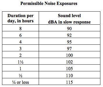
To design for the most conservative standards, we assume that emergency personnel are in an ambulance and exposed to its sounds for an average 8 hours each day. Our system therefore needs to maintain sound levels < 90 dBA in order for ambulance personnel to be present without required hearing protection.
As a medical tool, the system must be easily cleanable and impervious to bodily fluids and other hazardous materials.
Temperature constraints are also important factor to consider. While the ambulance is in use, with patients and or medical personnel inside it, the internal temperature will be regulated by on-board air conditioning and heating systems, as you’d expect. However, our product will still be in the ambulance while it is parked and not in use. Therefore, we must consider the temperatures the ambulance will undergo when parked in both the winter and the summer. The coldest recorded temperature in Maryland is -40°F. Although the interior of the ambulance will likely be slightly warmer than this, this number serves as a good lower temperature bound approximation and defines the coldest temperatures our system would be expected to survive. In the summer, parked vehicles can get up to 140 degrees Fahrenheit, even when the surrounding air temperature is much cooler. It is vital, therefore, that our product be designed to survive in such extreme temperatures without any degradation or increased risk of material failure.
These restrictions limit the size, power draw, and noise level of our apparatus and must be considered throughout our design. These are not, however, the only constraints or standards we must adhere to. The Commission on Accreditation of Ambulance Services denotes requirement
C.11.1.1 (Mounting and Location of Medical Equipment and Supplies): “For any equipment and materials over 3 lbs, not otherwise stowed in a cabinet, equipment mounts or retention devices shall be utilized. The mounts or retention devices shall be installed according to the mount or retention device manufacturers directions. These mounts should be tested in accordance with the requirements of SAE J3043 (Ambulance Equipment Mount Device or Systems). The purchaser shall specify to the manufacturer the desired location and structural requirements for mounting equipment. The manufacturer shall place an appropriate structure in the vehicle to provide support for such an installation.”
The standard referenced here, SAE J3043, describes the dynamic and static testing procedures required to evaluate the integrity of an equipment mount device or system when exposed to a frontal or side impact.
The Design
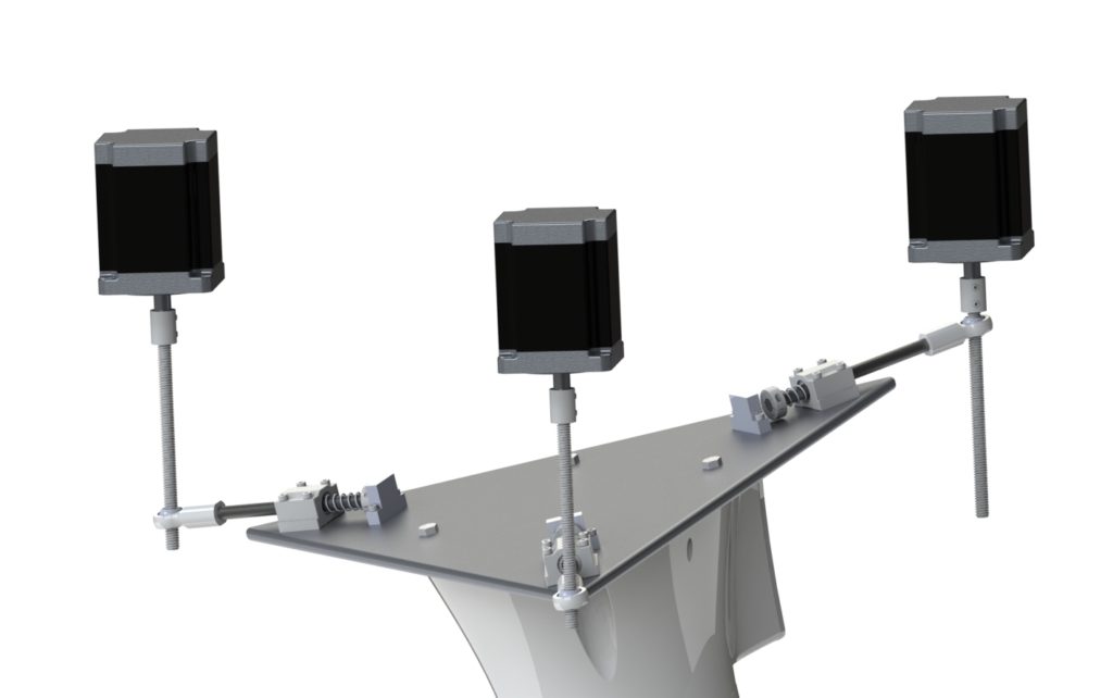
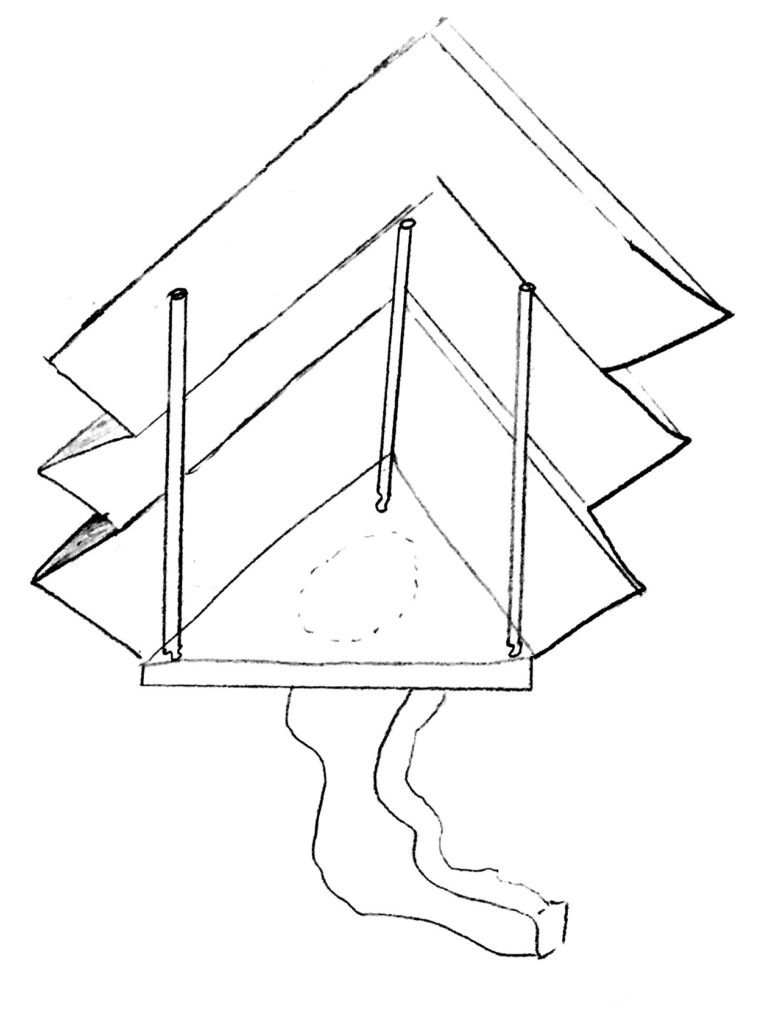
The system, broadly speaking, involves five major subsystems: the robot, platform, spring shaft assembly, stepper motors, and the sensing/control system.
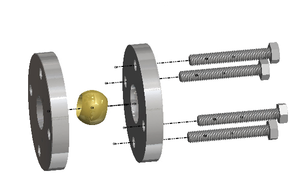
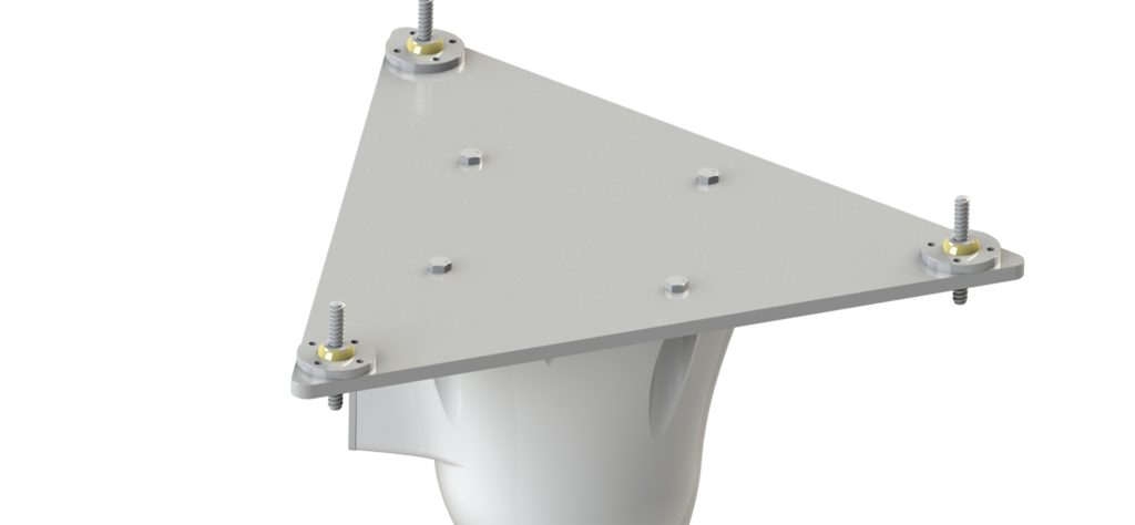
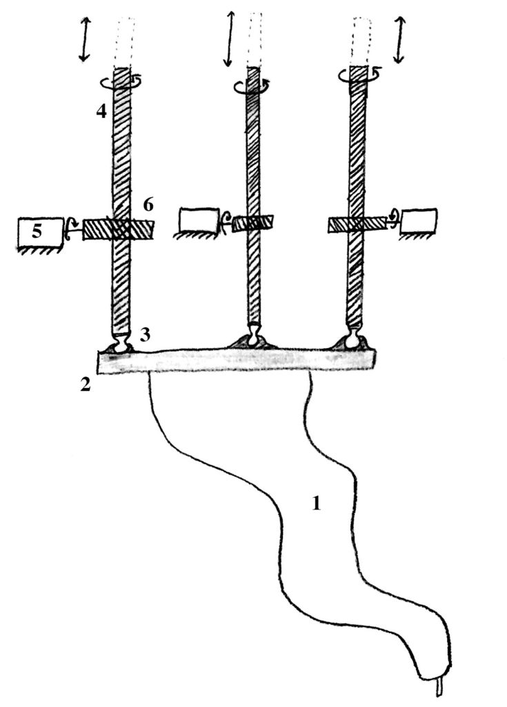
The robot is mounted to a stiff triangular platform via four M8 bolts. Each corner of the platform has a spring-loaded shaft assembly, shown below.
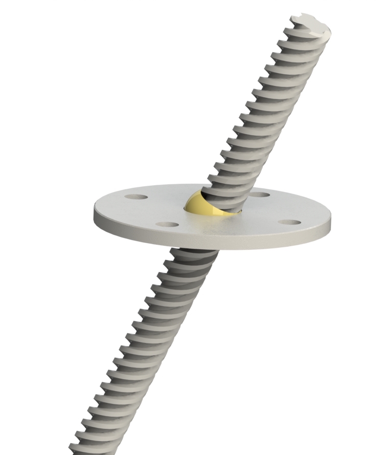
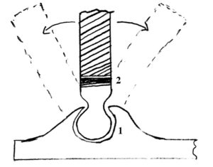
The shaft is male threaded at one end and mated with a female threaded heim joint. A heim joint is a mechanical articulating joint with a ball swivel, and provides flexibility in the platform’s angle. The inside of the ball swivel is threaded with ACME threads, the screw type commonly used for lead screws. A matching lead screw is threaded through this hole and connected to a stepper motor via a flexible coupling. The motor is then mounted on the ceiling of the ambulance above. As the motor spins, the heim joint travels either up or down on the screw, adjusting the height of its corner of the platform. By precisely controlling the three motors at different speeds, we have near perfect control over the pitch, roll, and height of the platform.
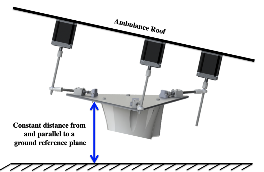
A 9 axis accelerometer and gyroscope combination sensor is mounted to the ceiling of the ambulance as the input to the system. An additional matching sensor is mounted to the platform as a system feedback, enabling closed loop control. With this sensing and motion capability, the system can adjust the position of the robot so that it always remains perfectly parallel to and equidistant from a constant ground reference plane. If the ambulance hits a curb, the roof will pitch upward, and the platform will pitch in the opposite direction to counter the motion.
Below is an animation showing the system adjusting the platform position from +thirteen degrees to zero (measured from the ground plane).
Here’s a quick animation of the platform moving up and down.
The shaft assembly frees the design from a pesky trigonometric length constraint – as the angle of the platform increases, the side length of the platform must also increase.
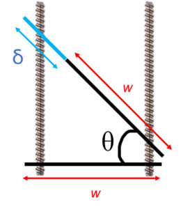
The length of the platform required to remain in contact with the screws increases as a function of θ, specifically L = w ∗ sec(θ), where L = w + δ. We can re-write this to create a function for δ:
δ = w(sec(θ) − 1)
With a side length (w) of ~500mm, we can evaluate this problem graphically in MATLAB.
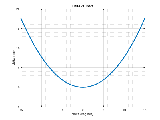
In order to tilt the platform even a meager 10 degrees, the platform length must change ~8mm. This flexibility is made possible by the spring loaded shaft assembly. The springs return the platform to its nominal position when flat.
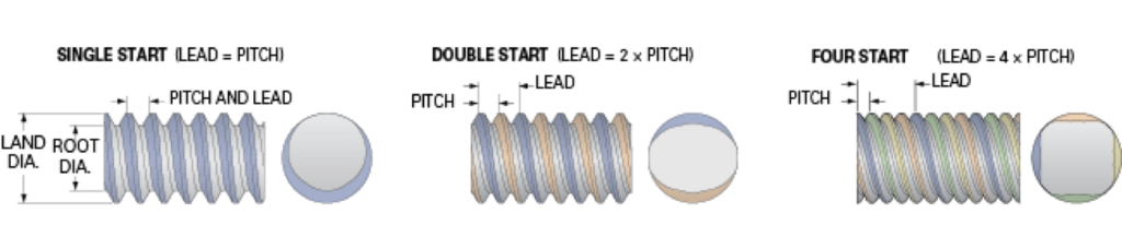
The system is designed to be scalable. It’s responsiveness, which correlates with the size and speed of impulses it can negate, can be scaled by adjusting several factors. The pitch of the lead screws can be made finer, allowing for more precise position adjustment. Each lead screw can be replaced with one with more starts – the number of independent threads. This changes the travel distance per turn, another metric for the precision of positioning. Fast travel screws can move further distances more quickly with the same rotation, but lose the fidelity of control that the single start screws (with much smaller travel distances) provide. Single start screws need to be spun much faster to cover the same distance (impacting the requirements of our motors), but can be positioned much more precisely than their multi-start counterparts.
The motors, sensors, and control system can similarly be upgraded for faster performance. With a faster system, more rapid impulses can be countered, broadening the use cases of this product.
Materials
The materials for each component were carefully chosen for a variety of properties. The platform is made of 6061 aluminum, chosen for its wide availability, easy machinability, and near infinite recyclability. The shaft is made of black oxide steel for strength and durability. The heim joints are similarly comprised of stainless steel. The lead screws, expected to bear the most stress throughout use, are designed to be Black-Oxide 4140 Alloy Steel, chosen for its high tensile strength.
Assembly Considerations
A easily overlooked facet of design is assembly. It is easy to forget, while working with digitally mated parts in CAD, that each component needs to be assembled in real life. There must room for screwdrivers and wrenches. The order a system is assembled matters too – some steps are easier when the system is resting on a tabletop instead of hanging in an ambulance. Ergonomics and and its affect on installation steps must also be considered, so as to not strain or injure the assembling team. The assembly order of this product was revised after we attempted to assemble our scale model prototype.
The steps for assembling this system are as follows:
1. Connect lead screws and motors
2. Mount the motor screw assembly to the motor plate
3. Mount motor screw plate assembly in ambulance
4. Wire the motors to the controller
5. Mount the ceiling accelerometer and wire it to the controller
6. Assemble spring mechanism assembly
7. Mount spring mechanism assembly on the platform
8. Mount the platform accelerometer to the platform
9. Bring platform into ambulance; thread lead screws through heim joints
10. Wire the platform accelerometer to the controller
11. Mount KUKA to platform
The system is designed to be modular and easy to assemble. The first step of assembly would be to connect the lead screws and motors via the flexible couplings. This can be done on a tabletop at a comfortable position for the operator, and involves tightening two set screws (per lead screw) with an Allen wrench. The flexible couplings have small bellows to allow for small lead screw misalignment.
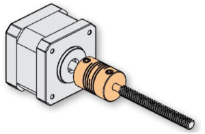
Sketch of the motor, coupling, and lead screw
Use the motor plate as a template to mark the locations in the ambulance ceiling to drill for the plate bolt holes. Each motor-screw assembly should now be mounted onto the motor plate. This plate fully constrains the positions of the motors and ensures they’ll be in alignment with the robot platform (to come later). It also facilitates install of this sub-assembly in the ambulance, which is the next step. Once this is complete, the motors can be mounted in the ambulance.
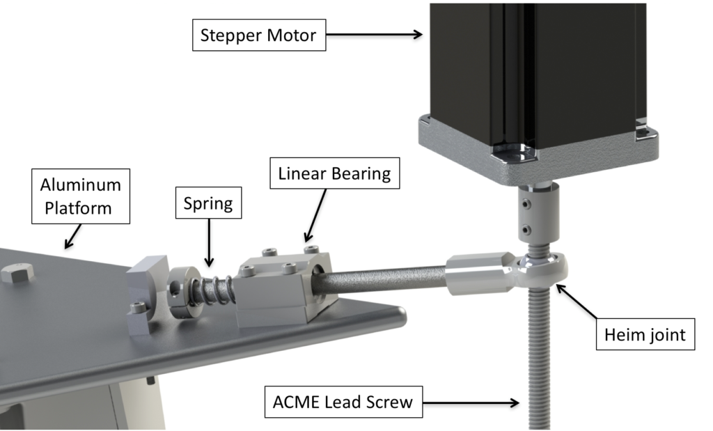
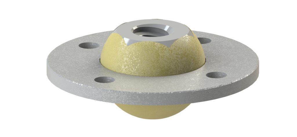
Assemble the spring mechanism assembly as shown in the figure below. This can also be done on a tabletop within comfortable reach of the operator. Start by threading the heim joint onto the end of the shaft and hand turn until tight. Next slide the first linear bearing onto the shaft. This one is shown in blue in the figure below. Similarly, slide on the second bearing and spring onto the shaft. Slide the collar on to the shaft and tighten it into place with the internal set screw. This can be done via an Allen wrench.
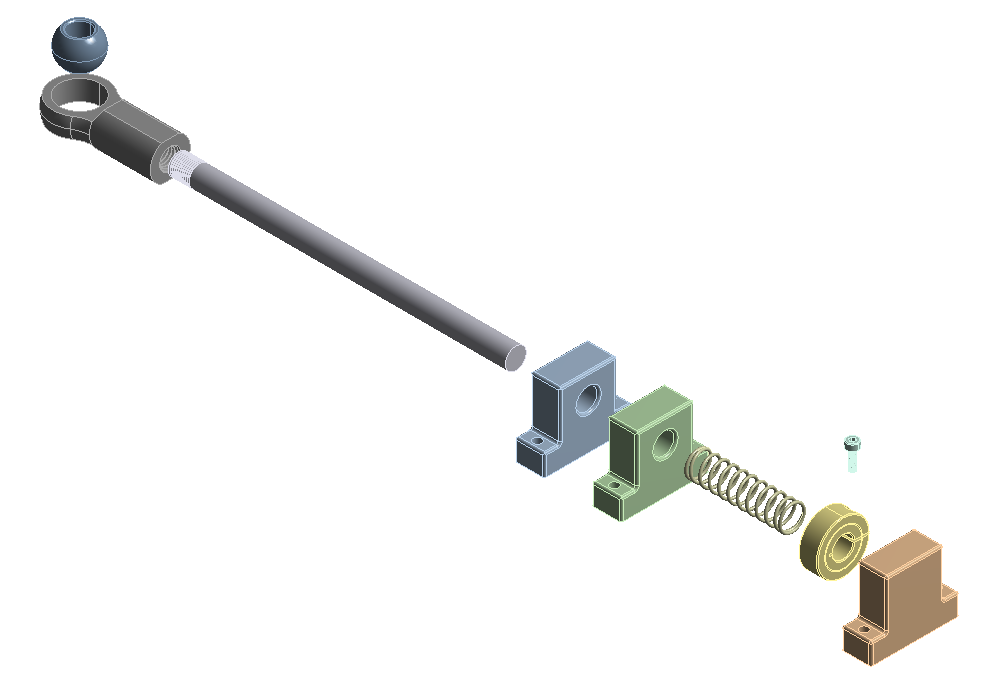
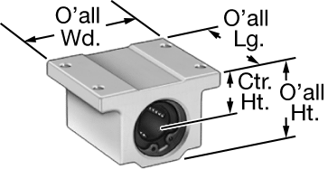
Note that the blue and green components in the above figure are actually one linear ball bearing like the one shown below. These allow the shaft to slide. The orange component is a shaft stop – a solid piece of metal that constrains the range of motion of the shaft.
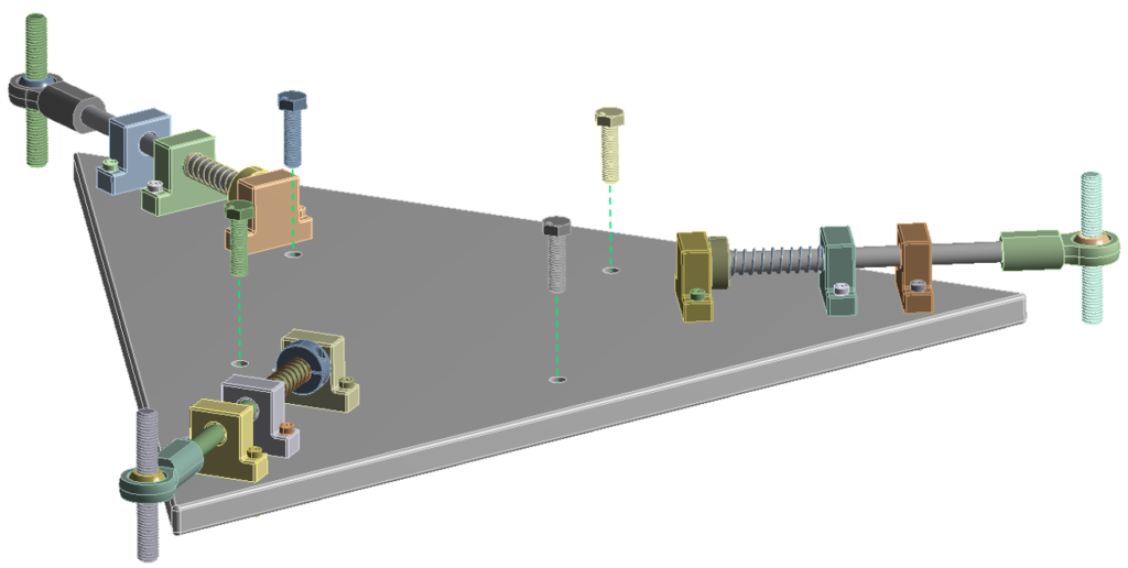
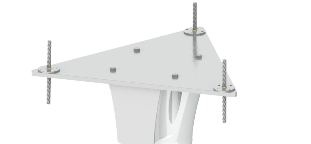
Now it’s time to mount each spring assembly on to the platform. Lay the platform on a table with one corner hanging over the edge. Align the orange shaft stop with its bolt holes, and pass the bolts through the platform. Thread a nut onto each bolt and tighten by hand and then tighten further with an Allen wrench. Align the spring assembly with the holes in the platform. Thread each bolt through its hole, and partially hand tighten each bolt. When the components are fully aligned, use an Allen wrench and a combination spanner to fully tighten the rest of the bolts. Repeat this for the other two corners.
Mount the platform accelerometer to the platform following the diagram printed on the platform. Now, bring the platform assembly into the ambulance. Thread each lead screw through its respective heim joint. This step may be easiest with one person holding the platform in position and another person helping to align everything. The KUKA is mounted to the platform via four M8 bolts and corresponding M8 nuts (not shown).
The KUKA weighs 22kg = 48.5lb. OSHA states that ”lifting loads heavier than about 50 pounds will increase the risk of injury”. It is inadvisable, therefore, for an individual to lift the KUKA for mounting on the platform, without external assistance, especially as this will require working in an awkward position over their head. The installation of the KUKA should be done by two persons working together with a jack, lift, or stand for the KUKA. One person should hold the KUKA to stabilize it horizontally and maintain it in the correct position, while the other individual inserts and tightens the bolts. The bulk of the KUKA’s weight should be supported by jack, lift, or stand. For ease of install, a ratcheting socket wrench is recommended to tighten the bolts. If available, a pneumatic socket wrench may further hasten and ease this step of assembly. Once the KUKA is secured, wire the accelerometers and motors to the controller.
Design for Manufacture
We also had to consider how each component of this system would be manufactured. As we went through the design process, our product structure evolved to become more easily producible. Complicated custom components were replaced with comparable COTS (commercial off the shelf) parts which could be sourced much more cheaply. The geometry of the platform was simplified to make it easier to machine, eliminating more complicated features and tighter tolerances which would’ve increased production cost and time. Some parts, like the shaft end and threaded heim joint, are still semi-custom. We changed our designs so these components could be sourced as COTS parts and then modified to fit our needs instead of being holistically manufactured in-house from scratch. Sub-assemblies were simplified were possible to reduce the number of independent components; for example, the two linear bearings on the shaft assembly were replaced by one longer bearing that served the same function.
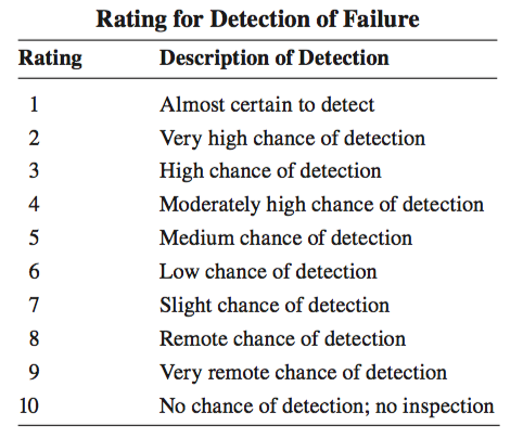
Failure Modes and Effects Analysis (FMEA)
Our team performed a comprehensive Failure Modes and Effects Analysis and evaluated every way we could imagine the system could fail. These failures were sorted by effects and rated on severity, detectability, and occurrence. The charts below were used to quantify each ranking and were excerpted from Engineering Design 5th Edition by George Dieter and Linda Schmidt (ISBN: 978-0-07-339814-3)
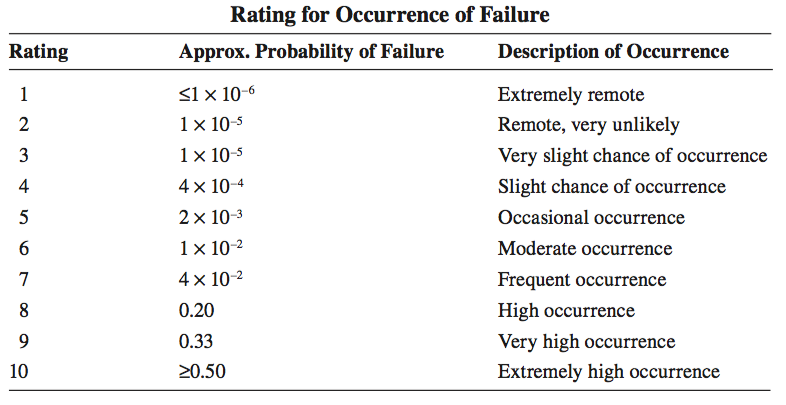
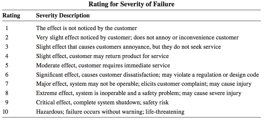
A thorough analysis of these failure modes and effects led to several design changes, some significant, some subtle. The Risk Priority Number (RPM=Severity*Occurrence*Detection) was used to prioritize design changes, with the highest value items posing the most risk to the system.
Design Evolution
The design process for this project was highly iterative. We started the semester with 60 conceptual ideas which varied in quality and feasibility. Through discussion and evaluation, we refined this list into 5 solid ideas that we believed to be achievable and worth pursuing. Further exploration and analysis whittled this list to our “final design”. This design underwent 6 in-depth comprehensive iterations, each building upon the limitations and issues of its predecessors. We learned the value of prototyping and evaluating ideas in the real world for validity, as well as the benefit of consulting with relevant field experts. At several moments in this process, we had developed a nearly fully fledged design before discovering some hitherto unnoticed flaw that made the design impractical or otherwise problematic. Below is a gallery of some of our earlier designs.
Works Cited
- [1] C. Hennersperger, B. Fuerst, S. Virga, O. Zettinig, B. Frisch, T. Neff, and N. Navab, “Towards MRI-Based Autonomous Robotic US Acquisitions: A First Feasibility Study,” IEEE Transactions on Medical Imaging, vol. 36, no. 2, pp. 538–548, feb 2017. [Online]. Available: http://ieeexplore.ieee.org/document/7637013/
- [2] H. Mo ̈nnich, P. Nicolai, T. Beyl, J. Raczkowsky, and H. Wo ̈rn, “A supervision system for the intuitive usage of a telemanipulated surgical robotic setup,” 2011 IEEE Inter- national Conference on Robotics and Biomimetics, ROBIO 2011, pp. 449–454, 2011.
- [3] S.-J. Lee, S.-C. Lee, and H.-S. Ahn, “Design and control of tele-matched surgery robot,” Mechatronics, vol. 24, no. 5, pp. 395–406, aug 2014. [Online]. Available: https://www.sciencedirect.com/science/article/pii/S0957415814000361?via%3Dihub
- [4] A. Vilchis, J. Troccaz, P. Cinquin, K. Masuda, and F. Pellissier, “A new robot architecture for tele-echography,” IEEE Transactions on Robotics and Automation, vol. 19, no. 5, pp. 922–926, oct 2003. [Online]. Available: http://ieeexplore.ieee.org/document/1236766/
- [5] A. Vilchis Gonzales, P. Cinquin, J. Troccaz, A. Guerraz, B. Hennion, F. Pellissier, P. Thorel, F. Courreges, A. Gourdon, G. Poisson, P. Vieyres, P. Caron, O. M ́erigeaux, L. Urbain, C. Daimo, S. Lavall ́ee, P. Arbeille, M. Althuser, J.-M. Ayoubi, B. Tondu, and S. Ippolito, “TER: A System for Robotic Tele- echography.” Springer, Berlin, Heidelberg, oct 2001, pp. 326–334. [Online]. Available: http://link.springer.com/10.1007/3-540-45468-3 39
- [6] P. P. Sengupta, N. Narula, K. Modesto, R. Doukky, S. Doherty, J. Soble, and J. Narula, “Feasibility of Intercity and Trans-Atlantic Telerobotic Remote Ultrasound: Assessment Facilitated by a Nondedicated BandwidthConnection,” JACC: Cardiovascular Imaging, vol. 7, no. 8, pp. 804–809, aug 2014. [Online]. Available: https://www.sciencedirect.com/science/article/pii/S1936878X14003945?via%3Dihub
- [7] “Interview with dr. hamed saeidi,” 2018.
- [8] S. Leonard, K. L. Wu, Y. Yonjae Kim, A. Krieger, and P. C. W. Kim, “Smart Tissue Anastomosis Robot (STAR): A Vision-Guided Robotics System for Laparoscopic Suturing,” IEEE Transactions on Biomedical Engineering, vol. 61, no. 4, pp. 1305– 1317, apr 2014. [Online]. Available: http://www.ncbi.nlm.nih.gov/pubmed/24658254 http://ieeexplore.ieee.org/document/6720152/
- [9] D. E. Clark, “RA cowley, the golden hour, the momentary pause, and the third space,” vol. 83, no. 12, pp. 1401–1406.