Foot Smasher
If you’re looking for the files associated with this project instead of this write up, you can find them here.
This system is a smash test apparatus for 3D printed prostheses to be used in ENME289P: Additive Manufacturing for Prosthetic Design. I designed and constructed it in the Fall 2018 semester and it serves as the successor to the original test apparatus designed and constructed by Saul Schaffer and Anna Packy. I took ENME289P the previous year, and worked with this original system during that course to test the prosthetic feet my team and I had designed.
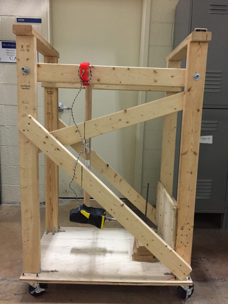
Original System
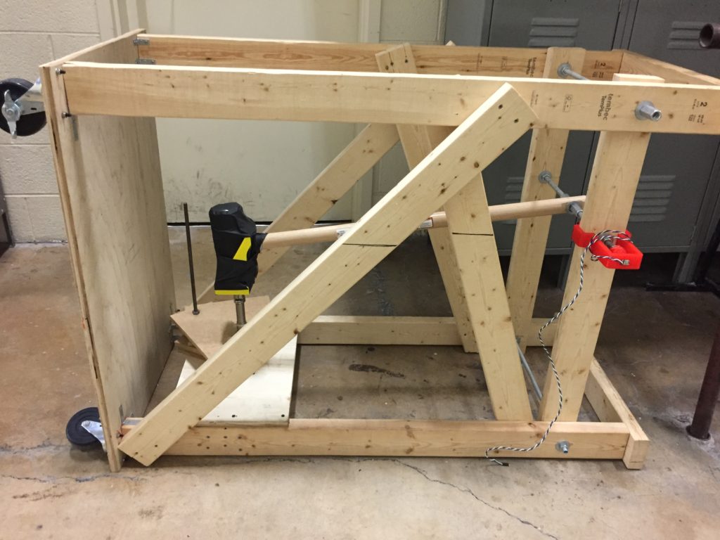
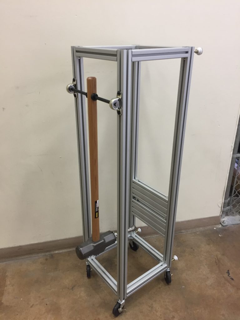
The original test apparatus (pictured above) consists of a sledge hammer attached to an axle mounted in a wooden frame. Attached to the head of the hammer is a pylon, when is then connected to a prosthetic foot. To test a foot is simple – lift the hammer to its vertical position, and then release it. It falls and impacts on the smash platform below, simulating the high impact of a child jumping.
Below is a video of one test of one of the prosthetic feet my team designed.
The results of this test lend the system its name – the Foot Smasher. That test was one of our team’s earlier prototypes. Later versions withstood the test without accruing appreciable damage. By viewing this (and subsequent) tests in slow motion, we were able to determine the weak parts of our design and rework our model until it could survive the test.
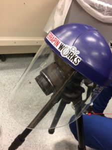
The test apparatus also included a potentiometer fixed to the hammer axle.
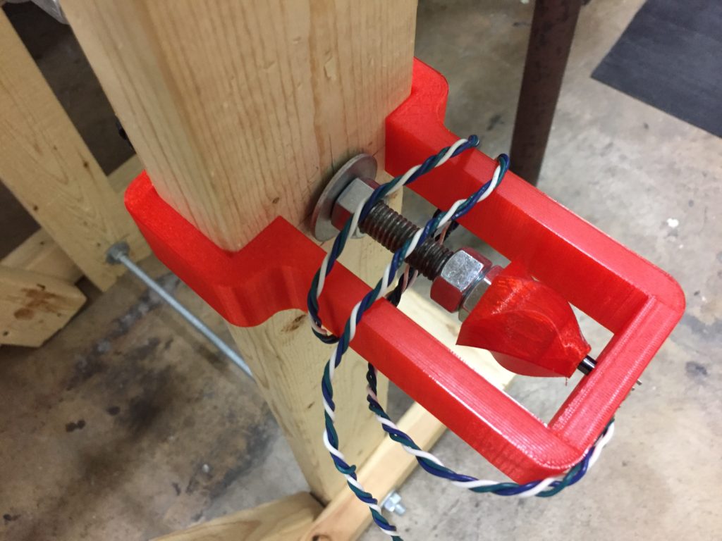
The idea here was that by reading the voltage across the potentiometer, we could map the position of the hammer head in time, with the hope of learning something useful about the impact and deceleration from this data. Unfortunately, the distance traversed by the hammer in its falling arc is vastly disproportionate to the distance traveled during the foot impact/compression, and any useful information about the collision gets lost in the noise of the data. Even when the system range was fine-tuned to a far tighter range of motion, it was difficult to learn much from the data collected. Much more useful to our foot design iterations was the qualitative information gathered from the slow motion videos of each test. While the quantitive approach of the potentiometer was a cool idea, it’s lack of practicality prompted me to abandon it in my redesign.
The system was built on a platform with caster wheels for ease of transport.
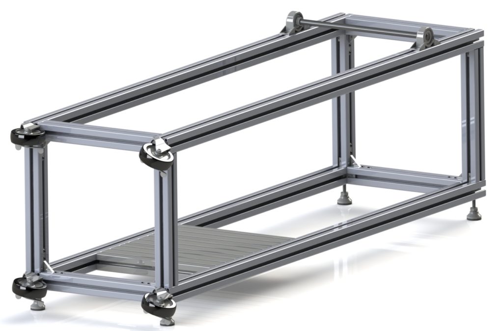
New Design
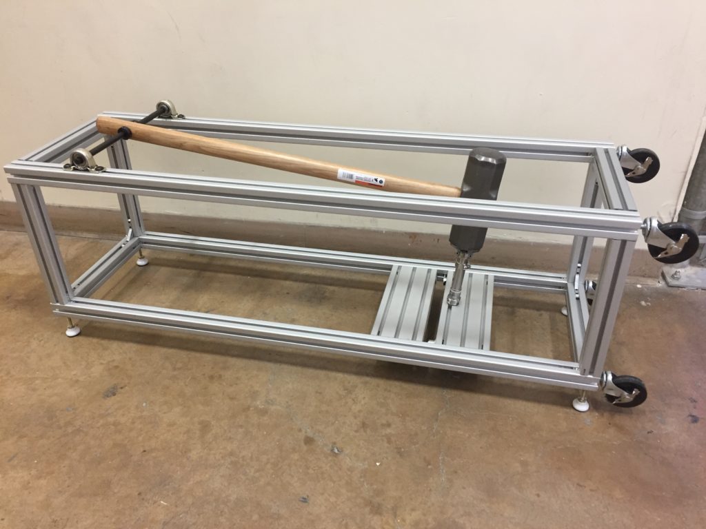
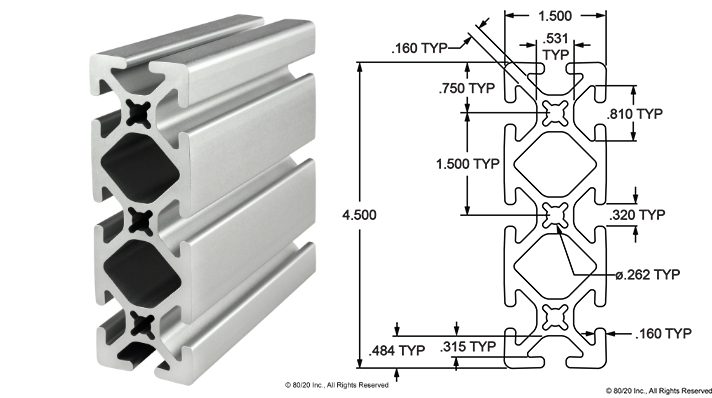
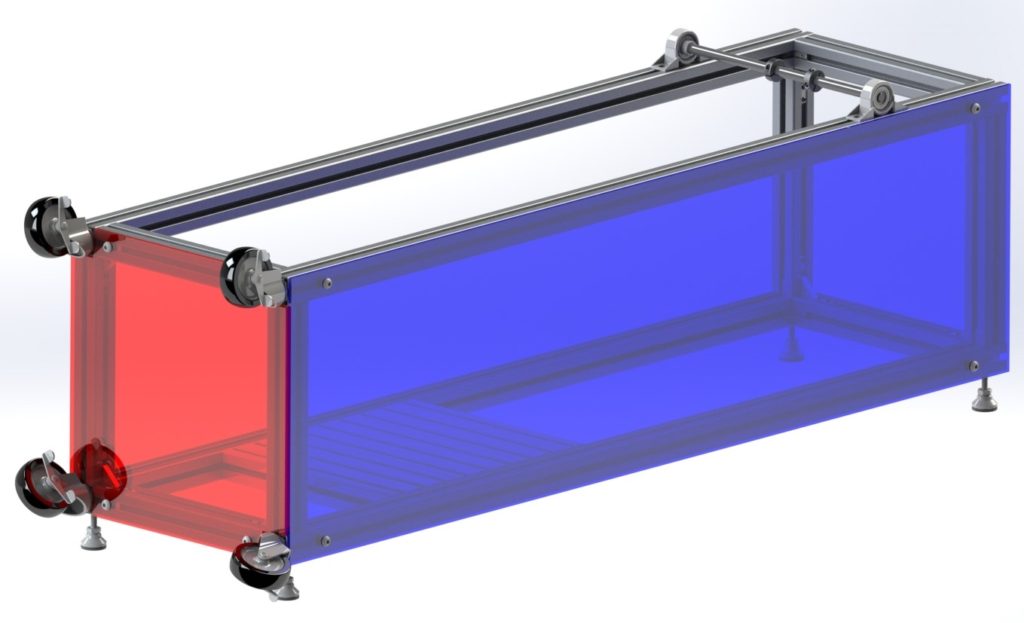
My redesign borrows heavily from the original system, and works in fundamentally the same way. The most obvious difference is the choice of construction material, with my redesign built out of 80/20’s T slotted profile aluminum extrusions. There were a number of elements I hoped to address with my redesign in order to make the system a better test apparatus for the class to use.
To start, let’s quickly explore energy loss. Below is a video from testing one of my team’s later prototypes with the original system.
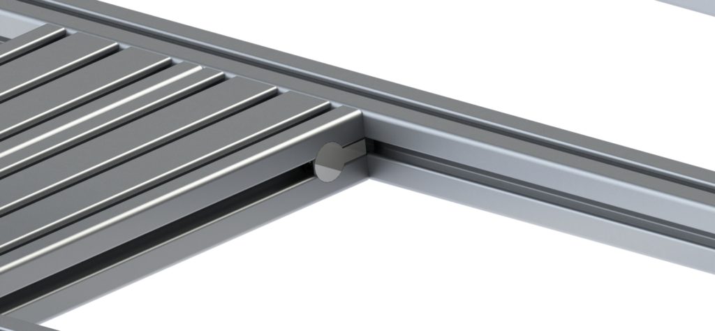
Note how high the smash platform bounces. This constitutes significant energy dissipated through this motion instead of through the foot, limiting the validity of the test. If you scroll back up and rewatch the earlier test, you’ll notice the platform bounces much less. The conclusion to draw here is important – the original test apparatus lacks repeatability, an element crucial for any scientific experiment. To combat this issue, I needed the smash platform to be rigidly affixed to the rest of the system. The new smash platform is made of two 80/20 triple wide 1.5″ beams, secured to the frame with anchors.
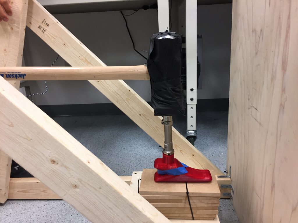
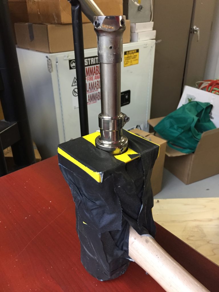
This change is the most obvious improvement in the overarching goal of enhanced structural rigidity. The original system used a 3D printed adapter to attach the pylon to the hammer head. This joint was reinforced with heavy tape. This solution was effective, but allowed some flexibility in the position and alignment of the pylon.
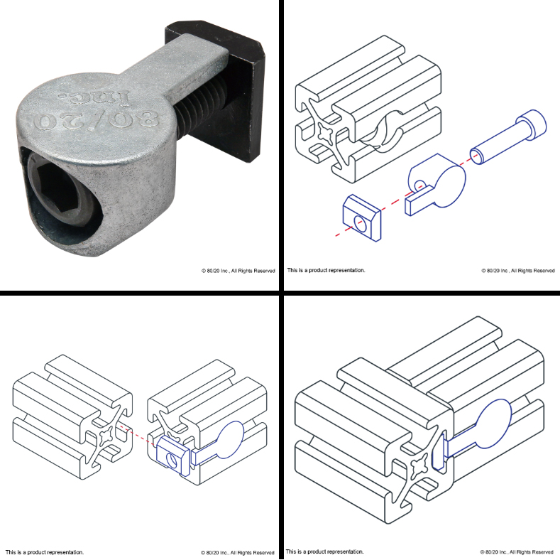
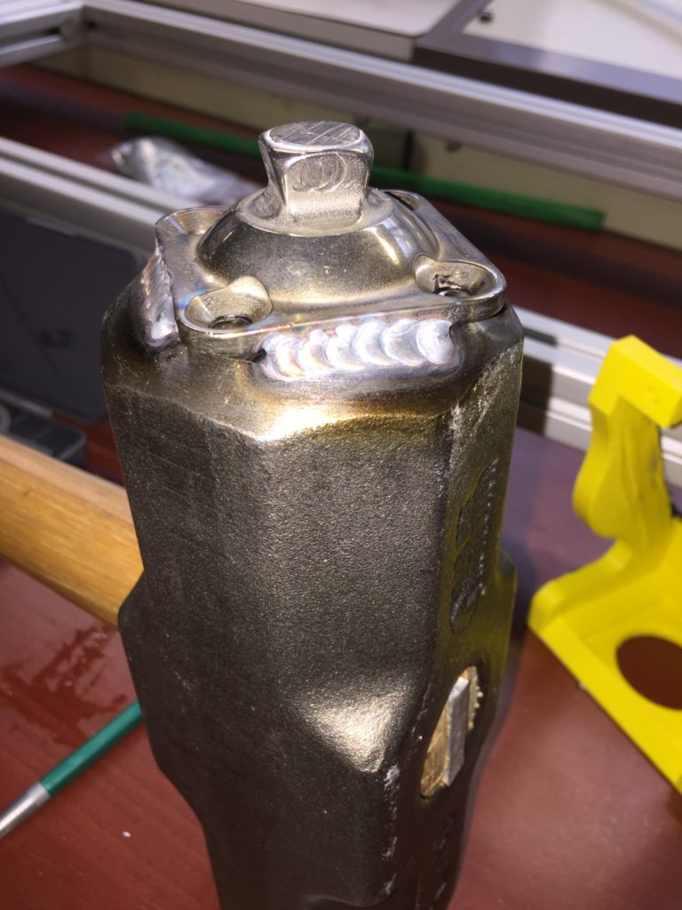
In the new redesign, the pyramid pylon adapter is instead welded to the face of the hammer, providing a solid interface for the pylon.
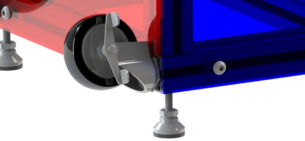
Like its predecessor, this design also includes caster wheels for ease of transport.
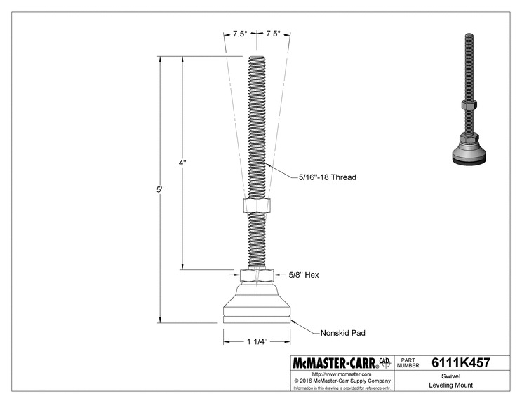
In addition, it also has self leveling feet, which provide an adjustable, stable, level platform for the system to rest upon.
This redesign was also intended to be much more compact than it’s predecessor. After carefully examining the system and its needs, I was able to design the new apparatus to be considerably thinner and shorter, allowing it to be stored and transported more easily.
Safety Considerations
The original system created high speed plastic shrapnel whenever a foot was tested. This posed a safety risk to anyone near the system, especially those closely observing the test. The risks were mitigated with protective eyewear for everyone in the proximity.
Protective gear, while a valid solution, requires active safety considerations from everyone around. Anyone who fails to don the proper PPE (either through negligence or otherwise), places themselves at risk. It is better therefore, for safety to be integrated into a design. With this in mind, I added impact resistant polycarbonate walls to the system.
I created a thorough instruction manual for the system that includes additional safety precautions and tips for safe use.
Design Evolution
When I started this project, I explored a number of alternative design configurations. One version of my ideas envisioned a mass on a vertical track instead of the swinging sledge hammer. The angle of the track relative to the smash platform would be adjustable to simulate either a heel strike impact or a toe strike impact, increasing the versatility of the system. This design also has flexibility in the masses used – the impactor mass could be swappable to simulate the impact of either a child and an adult. Similarly, this plan included a damped smash platform (with potentially adjustable or swappable damping) to simulate additional types of impact.
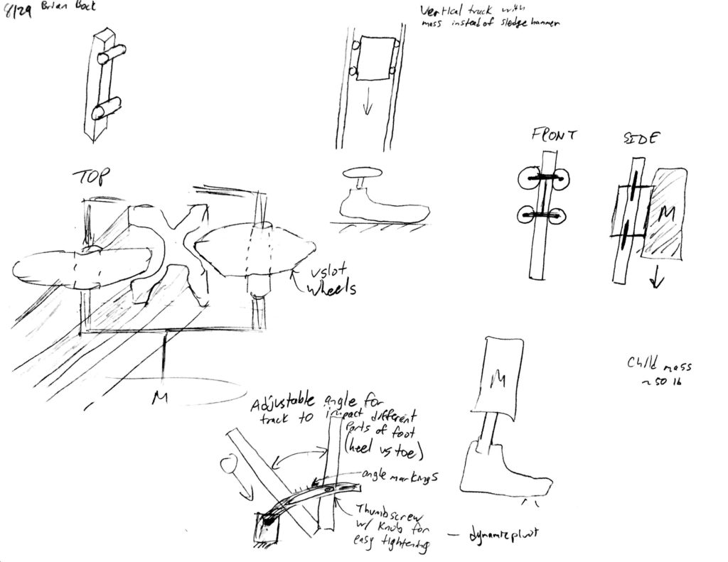
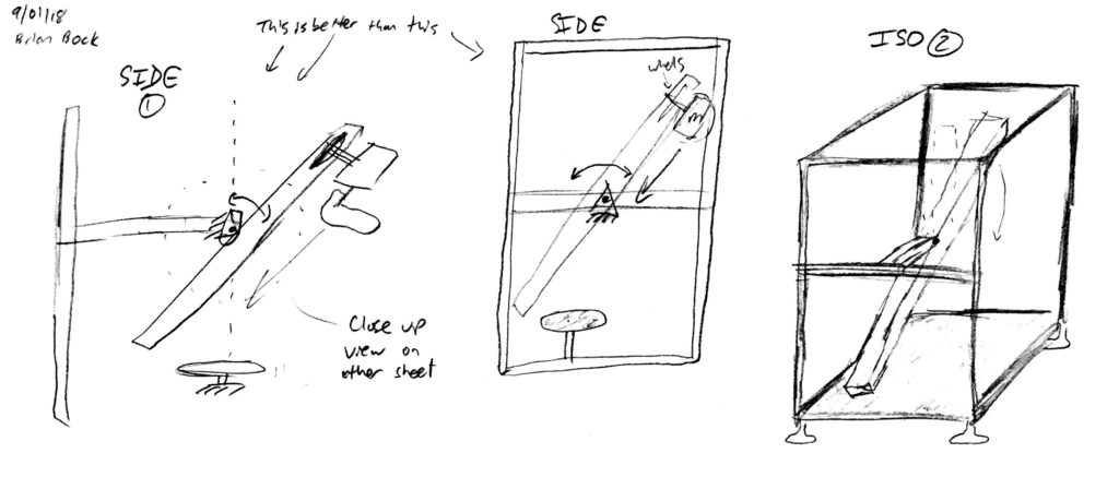
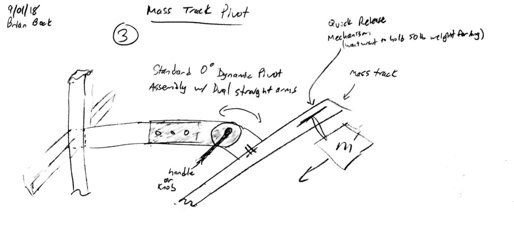
This design required the impactor mass to be mounted on a wheeled carriage, an assembly which dramatically increased the cost of the system. The angle adjustable track and damped smash platform also made this design prohibitively expensive.
In an effort to make the test apparatus produce more quantifiable results, I briefly explored a vibratory system, wherein the impact mass/foot would collide with a cantilevered beam. By measuring the beam’s deflection and dynamic response with carefully calibrated strain gauges, Dr. Mitchell and I thought we might be able to extrapolate information about the elastic and damping properties of the foot. However, as we explored the issue further, it became clear that the technical challenges presented in this concept far exceeded the scope of a single semester project. Anyway, the qualitative slow motion videos proved to be much more formative to our foot designs than the data we gathered, so the need to pursue a more rigorously quantitative design was minimal.
Acknowledgements
I’d like to thank Mr. Majid Aroom, for his help and guidance in the machine shop, as well as Howie in the Aerospace machine shop for welding the pyramid to the hammer. In addition, I’d like to thank Saul Schaffer for suggesting this project and Dr. Steven Mitchell for overseeing my work on it.