I built an automated Nerf gun. First, let’s start with a video overview and demo:
Parts
| Part | Source | Qty | Total Cost |
| Nerf Doublestrike | http://a.co/3KRslxj | 1 | $9.97 |
| IR Sensor | https://www.dfrobot.com/product-1088.html | 1 | $23.55 |
| 6001HB Servo | https://www.pololu.com/product/1056 | 2 | $25.90 |
| Arduino Uno | 1 | ||
| Breadboard | 2 | ||
| Piezo Buzzer | 1 | ||
| USB DC Barrel Cable | https://www.amazon.com/Uxcell-Barrel-Power-Cable-53832/dp/B00304DZ7I | 1 | $4.33 |
| DC Barrel Power Adapter | https://www.pololu.com/product/2449 | 1 | $1.95 |
| IR LEDs | http://a.co/ap3WCRX | 1 | $7.75 |
| Battery Pack | http://a.co/3O6nQRN | 1 | $9.99 |
| 330 Ohm Resistor | 1 | ||
| Misc Wires | |||
| Bolt | https://www.mcmaster.com/#92245a574/=1cbr3tq | 1 | $5.71 |
| Nut | https://www.mcmaster.com/#95505a611/=1d3yemy | 1 | $3.75 |
| Zip Tie | |||
| Tripod | http://a.co/7iJRTYn | 1 | $23.50 |
I already had the Arduino, buzzer, DC barrel adapter and USB cable from prior projects. Breadboards, resistors, and piezoelectric buzzers seem to come with most Arduino Starter kits, so they shouldn’t be too hard to find for cheap. You don’t need these specific LEDs or battery pack – any comparable ones you have should work fine. You’ll need some M-M wires and some M-F wires to connect everything.
I sized the bolt based on nuts I had left over from a previous project. You certainly don’t need the 100 pack that they come in. Feel free to use a smaller bolt if you want – it’s just there to help hold the blaster in place.
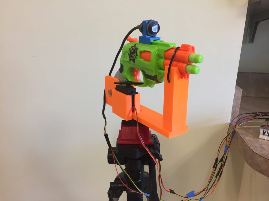
The blaster mount, IR Camera mount, and servo tripod mount were modeled in CAD and should be 3D printed. I printed all three components on a 5th Gen Makerbot Replicator, with default settings. You can access the parts and code for this project at: https://github.com/BrianBock/ANTS
Assembly
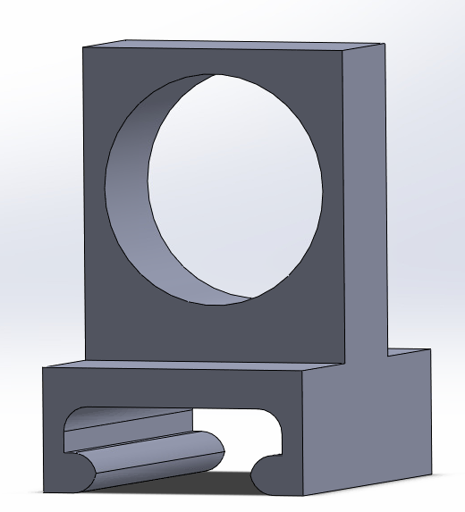
The assembly is pretty straight forward. The underside of the blaster mount has a cutout for the servo horn. Depending on your print quality, you may need to clean the cutout up a bit, but then the horn should fit nicely.
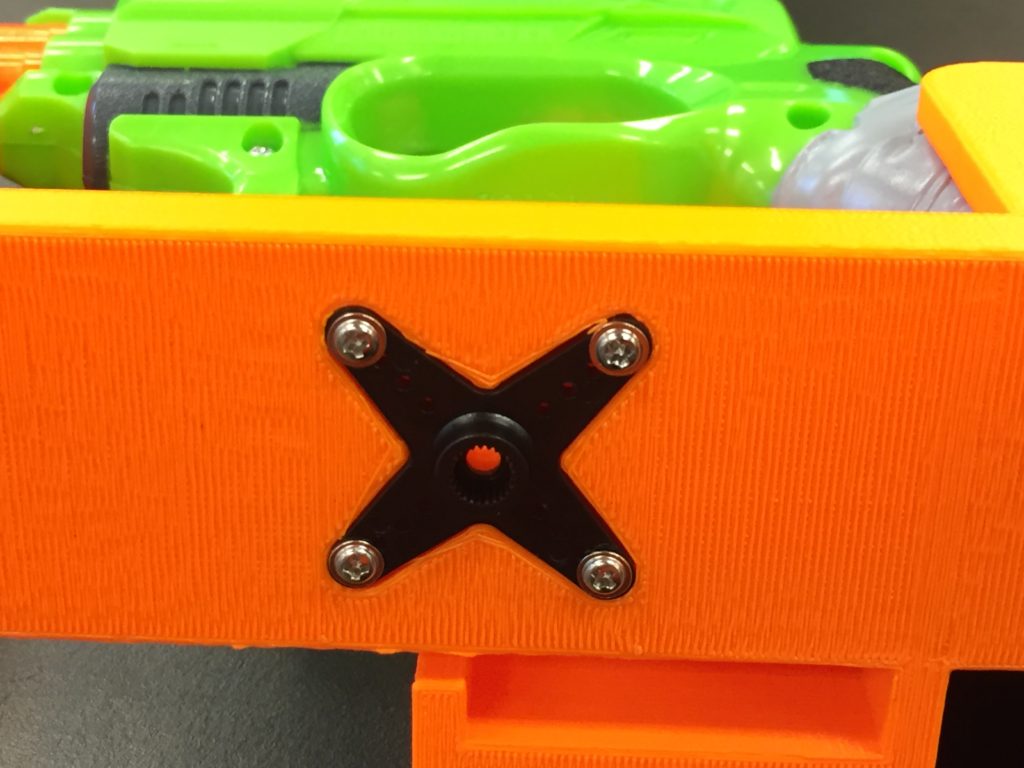
You can use the tiny screws that the servo comes with to affix the horn to the print. There aren’t any screw holes in the model – you just need to force the screws it (which isn’t actually too hard). If you don’t have these screws, you could probably hot glue the horn in place.
You need to drill a hole in the blaster for the bolt. You can use the mount as a guide. It’s a ¼” bolt, so a ¼” drill bit (or the next size larger) should work. Feed the bolt through the hole and hand tighten the nut on the bolt.
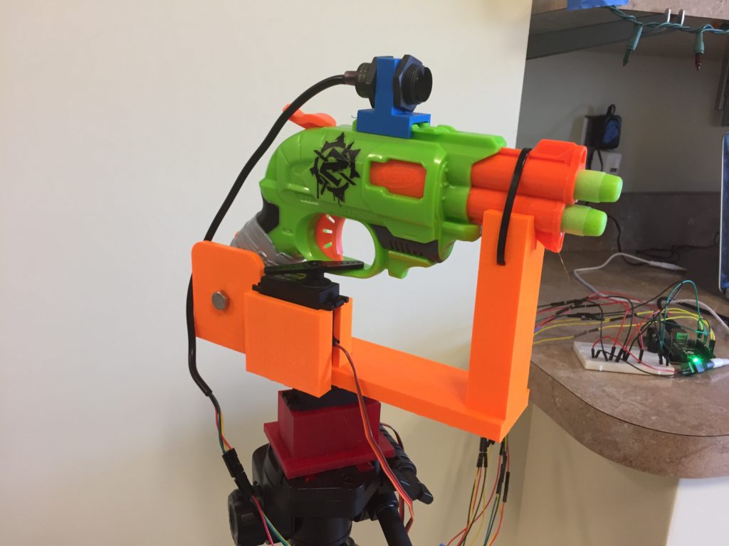
The tripod mount replaces the original tripod plate and clicks into the tripod exactly the same way. With the cutouts for wires, each servo can only fit one way. The two servos are identical, so it doesn’t matter which one is the trigger or the bottom servo, so long as you wire them to the Arduino carefully. It may be advisable to run the system before attaching the trigger horn, to make it easier to align. You want the trigger horn to stick through the trigger finger hole and turn to fully compress the trigger. Check out the video again to see that up close.
The IR sensor mount is symmetric and slides onto the tactical rail.
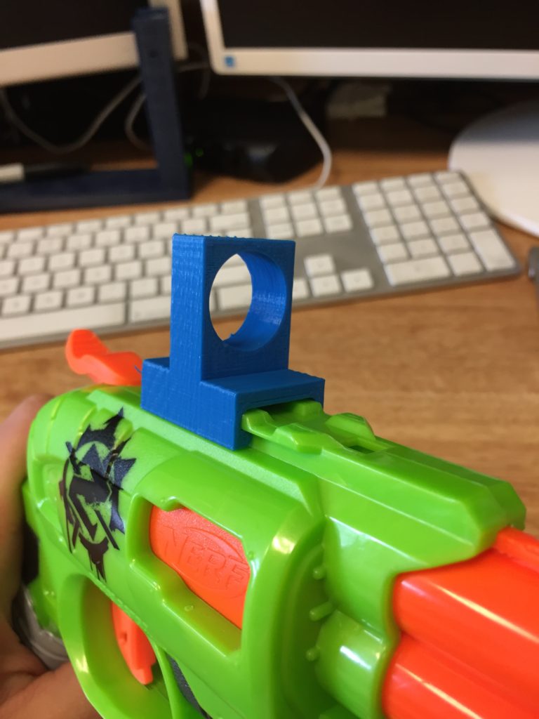
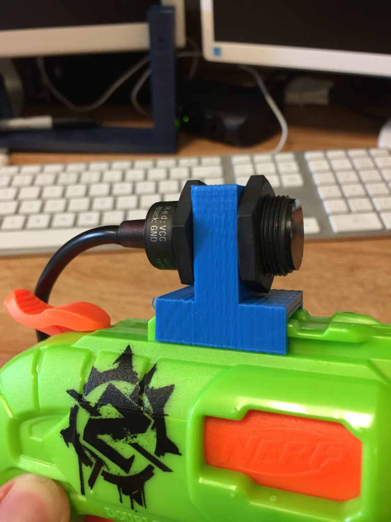
The sensor comes with two plastic nuts, which you’ll hand tighten on either side of the mount to hold it in place. It’s important that you mount the sensor with the sticker labeled “Top” facing up. If you don’t, any values you record will come in sideways and the system won’t work well.
Wiring
The wiring is actually pretty simple.
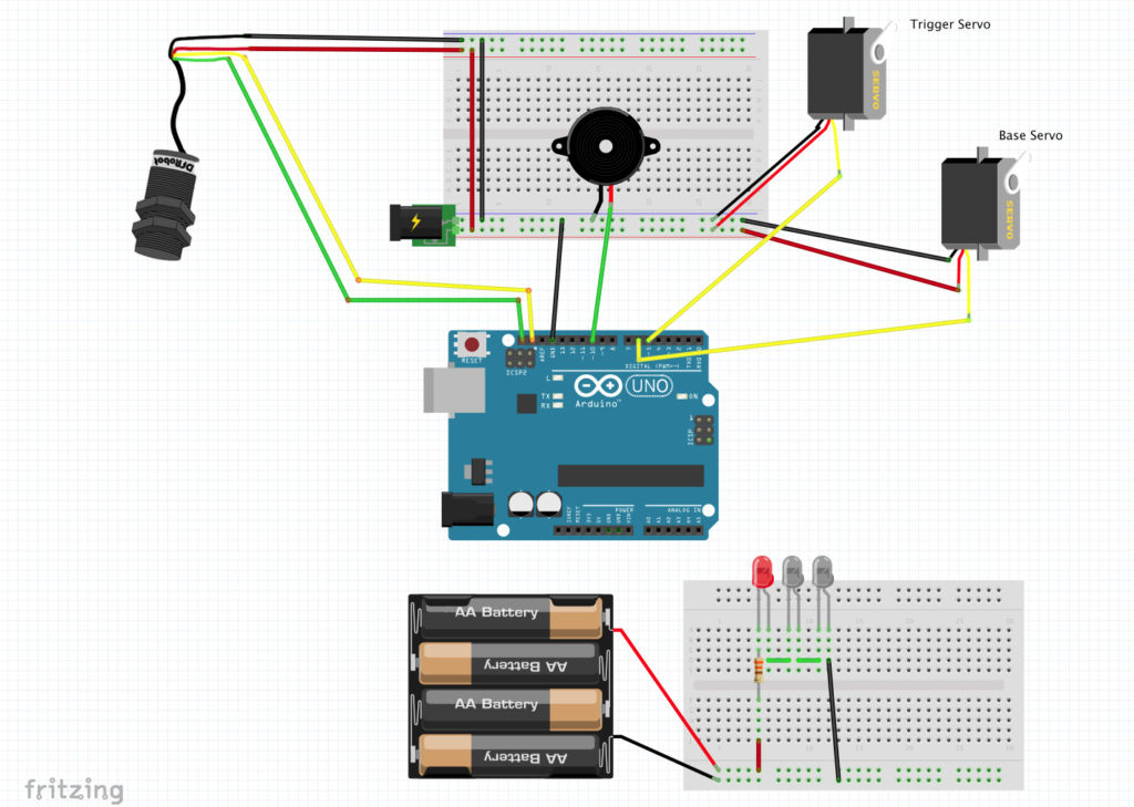
The servos require too much power to be driven simultaneously by the Arduino, which is why I used the USB DC barrel adapter.
Be very careful not to connect the Arduino 5V or 3.3V to the 5V of the adapter! Servos have 3 wires – Brown/Black, Red, and Orange (or Yellow). As usual, black/brown goes to ground, red goes to your voltage source, and orange goes to the Arduino, If you switch the brown and red wires, the servo will short and very quickly be rendered useless (and smell like burning plastic). Check your wires carefully. I used a bunch M-F wires to extend the servo cables to comfortably reach my breadboard on the table. If you have long cables, it might be better to use those instead, for simplicity.
The sensor returns the coordinates of the first IR light it sees, and then the base servo turns until that point is within a tolerance of it’s center of field of view. I found it really helpful to wire a Red LED in series with the other IR LEDs, as the only practical way to verify that the lights were on and working. I experimented with a couple of different resistor values. The higher the resistance, the dimmer the lights are and the shorter their effective range becomes. 330 ohms seemed to work well for range of a few feet. If you have an IR flashlight or other IR light source, there’s no reason to build the light portion of this project.
The Processing code displays a Red dot corresponding to the location of the IR light it sees, and also displays the system’s status. When dot falls within a range of the center, the trigger servo pulls the trigger, firing the gun. Arduino will play a little victory melody on the buzzer. When it finishes, you should hit the reset button on the Arduino, relaunch the Processing program, and pull back the blaster hammer to prime it to fire again. Be careful to hold the mount when you pull back the hammer so that you don’t torque on the base servo.
That’s pretty much it! You’ve got a turret ready for the great Nerf War.