Geckogator
As part of the Bio-Inspired Robotics course (ENME489L) at the University of Maryland, I worked as a team with three other students to design a Gecko inspired robot. I would be remiss in this writeup if I did not recognize the contributions of my team: Amirka Souhlal, Ryan Moss, and Marieanne Bonnefoy, without whom this project would not have been possible. They each deserve equal credit for the ideation, evolution, and progression of this project. Dr. Axel Krieger, our instructor for this course, was a very valuable resource to us throughout the semester. This writeup walks through the project requirements and limitations, some of our design evolution, and our final working design.
The Task
The goal of this project was to create a walking robot (mimicking a real animal gait) capable of traversing 35x its own body length in 2 minutes or less. The robot had to be able to walk on smooth hard floor and short carpet.
Available Parts
1 Arduino Uno (or Nano)
9 High Torque Metal Gear Micro Servos
9V Battery
6V 2000mAh NiMh Rechargable batttery & Charger
Misc wires
The Gecko / Alligator
Our first task of this project was to determine a suitable animal gait to mimic. After some research and exploration, we decided to pursue a hybridized gait based on both a gecko and alligator, yielding the robot’s name, the Geckogator.
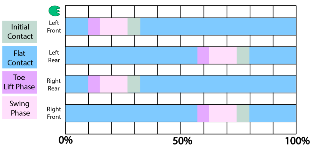
You can view a gecko walking in this video: https://youtu.be/AqxLS_Gtc-I. The gecko walking low gait is comparable to a mammal trotting gait. The gecko alternately moves two legs at a time, either the front left leg paired with the back right leg or the front right leg paired with the back left leg. This gait is portrayed in more detail through a gait chart below. This style of locomotion is fast yet stable, and the time between leg swings helps keep the body balanced on the ground. The low walking gait maintains the body close to the ground, which adds additional stability to the gait type.
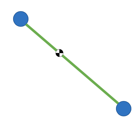
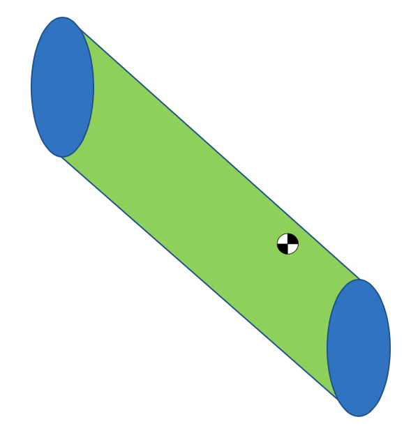
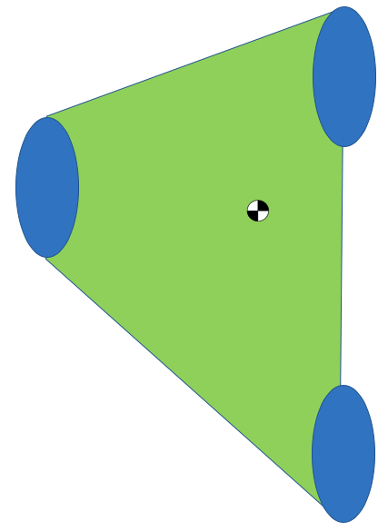
Stability & the Convex Hull
For this project, we were only concerned with static stability, based on the slow speed of our actuators. Static stability is relatively simple. In order for something to be stable, its center of mass must lie between the contact points (feet) on the ground. Wider feet provide a larger region of stability, as do additional points of contact.
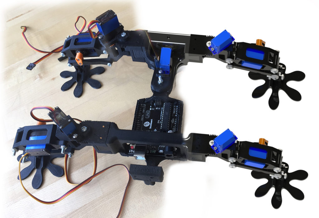
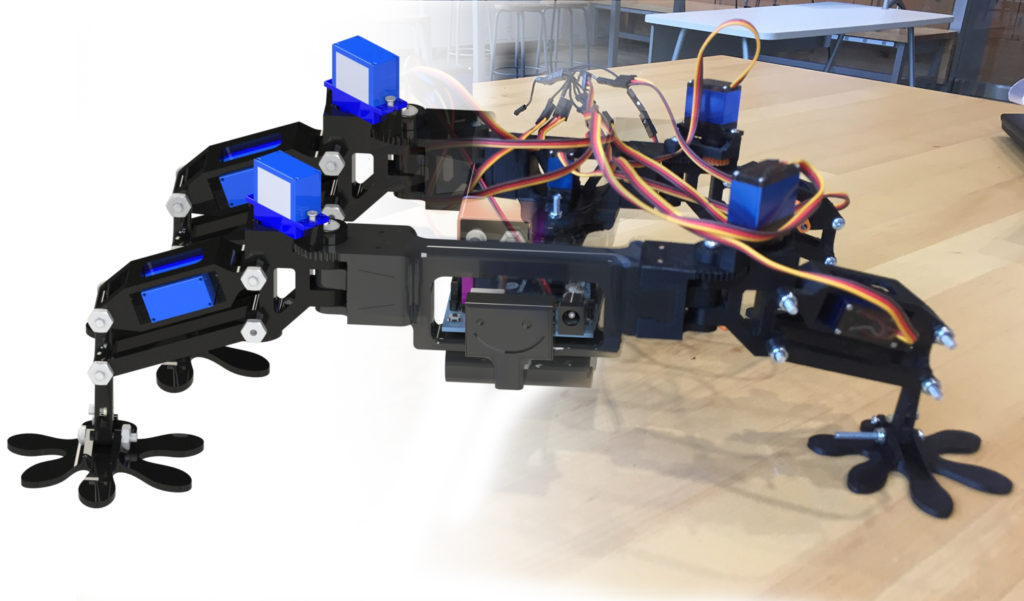
Final Design
The robot was designed with modularity in mind. Each leg connects to the body using a dovetail interface and is locked in place with ABS filament.
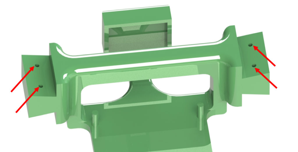
The remainder of the body is held together using screws and bolts to allow for disassembly and hinge rotation.
Main Body
To allow for body undulation, the main body is divided into two sections: the torso and hips.
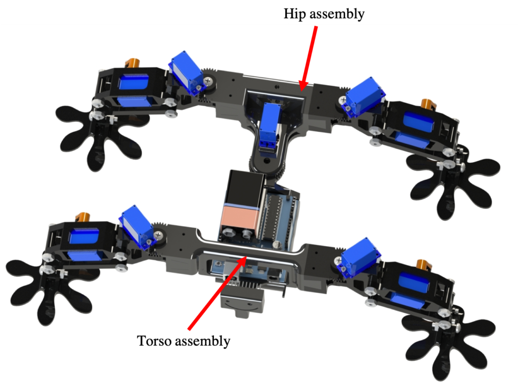
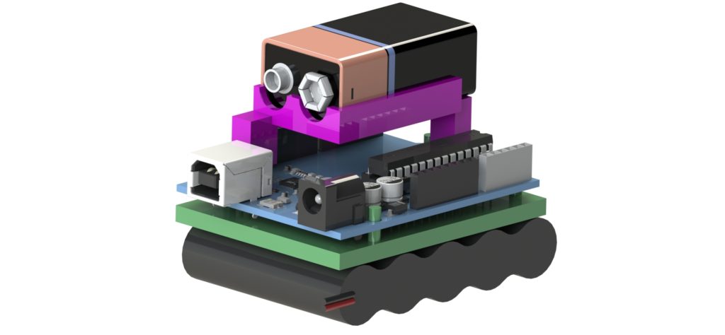
The head extends from the torso and houses the sensor. The center of the torso houses the Arduino, as well as the 9V and 6.6V batteries.
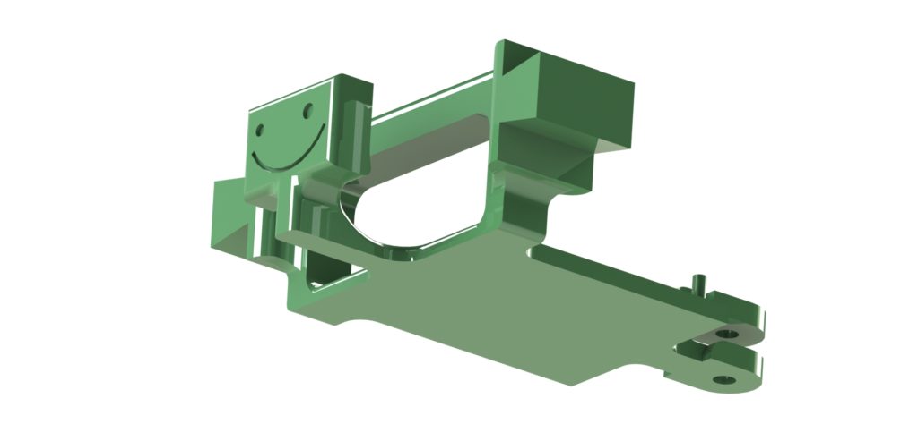
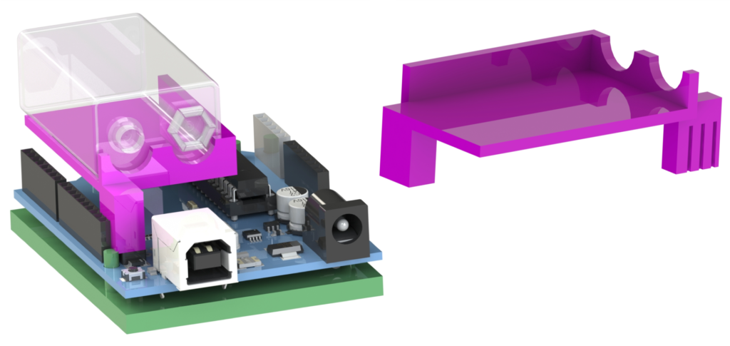
We actually found it difficult to connect the Arduino’s USB cable while the Arduino was flat on the plate (secured with the green pins). The head geometry made clearance to that port tight, so we lifted the Arduino off the plate whenever we wanted to upload new code. If we were to redesign the chassis, I’d redesign the head/neck position to allow for better cable access.
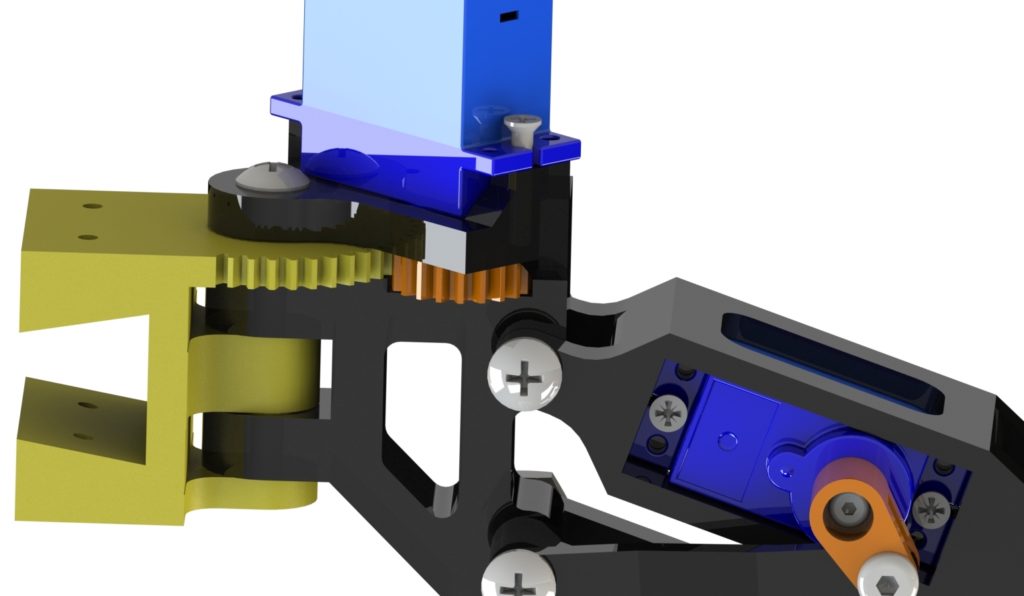
The torso and hips are connected with a geared servo, which is actuated by a hip-mounted servo.
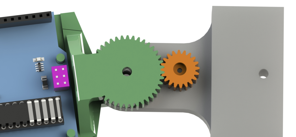
In order to maximize the servo range, both the body undulation servo and the leg sweep servos interface with 2:1 gearing integrated into the 3D printed body.
Legs
Each leg is comprised of one sweep servo and one lift servo. The lift servo is connected to a linkage system which allowed the leg to remain perpendicular to the ground regardless of leg height. Each sweep servo was mounted and positioned to obtain the maximum range while avoiding leg overlap. A rubber band Achilles tendon was implemented to maintain plantar flexion with the ground.
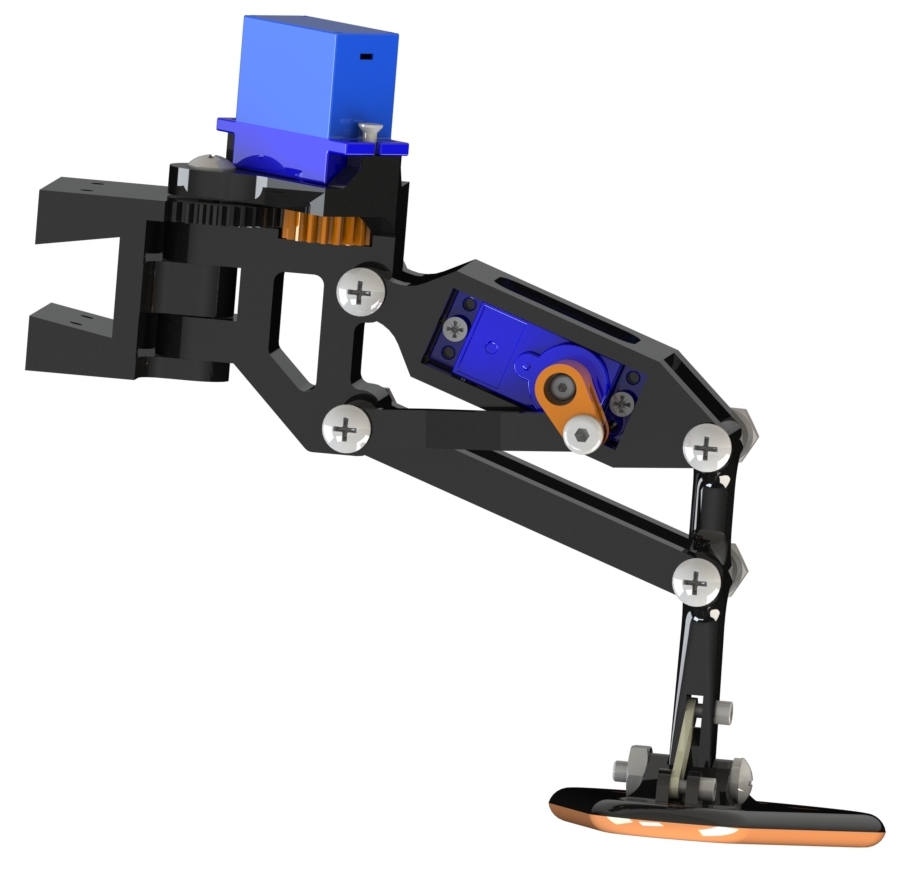
All the linkages are pin connected with screws, and free to rotate within that degree of freedom.
Each leg has a movement sequence with four actions: lifting up, sweeping forward, lowering down, and sweeping backwards. This sequence successfully simulates the movement an individual gecko leg makes during a full leg swing phase. Each alternating leg pair sweeps forward while elevated above the ground to reach ahead of the body. After sweeping forward, the leg plants itself on the ground and sweeps backwards to move the body forward. The eventual gait developed for the project diverges from the biological source in order to optimize for speed and stability.
Feet
We experimented with several different layers attached at the bottom of the feet to provide better grip with the ground – both smooth and textured Ninjaflex and Cheetah. Both smooth materials worked the better than their textured counterparts on hard smooth floor, and were all about comparable on carpet. Smooth Ninjaflex had the best grip of all “shoes”, but its effectiveness varied on the surface and it’s cleanliness – dust on the floor dramatically reduced grip. While this “shoe” had the best grip, it was only effective with significant downward pressure (normal force), which our lightweight robot was unable to provide. For our final tests, we replaced the grip shoes with a thick layer of hot glue, which provided more reliable grip on both floor surfaces.
We iterated through 3 successive foot designs for the robot. The first foot was large and rounded, designed to maximize our stability region.
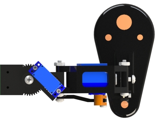
We later discovered that pita bread is sometimes sold in a very similar geometry and size, which lead us to nickname this design the “bread foot”.

While this foot was great for stability, it was actually too big for our robot. At the extreme ranges of leg motion, the front and back feet would step on each other, which is obviously problematic for walking.
Our redesign changed the foot geometry to limit this problematic overlap. Taking additional inspiration from our gecko, we designed feet more true to the gecko. These gecko feet became our primary feet for testing and were used for our final walking tests.
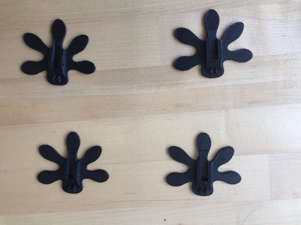
The gecko feet interface via the same geometry as the bread feet, and also utilize a rubber band Achilles tendon.
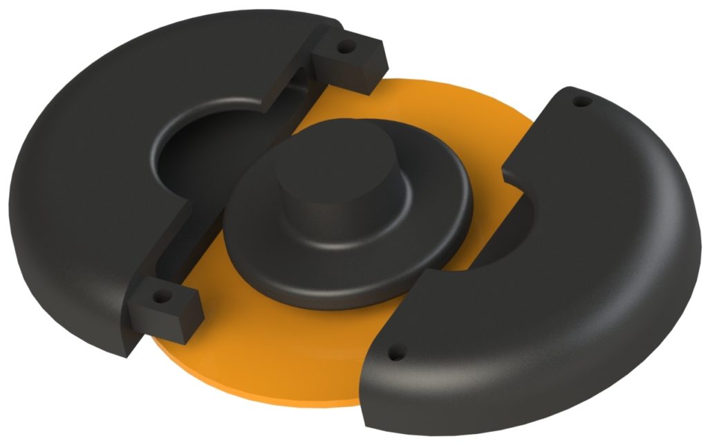
Dr. Krieger suggested we develop new feet that allow for rotation about each leg, to better match the gecko’s gait. This would allow for body undulation by permitting the feet to rotate while still maintaining a large contact area with the ground. We devised new feet (the “spin feet”) to accommodate this consideration.
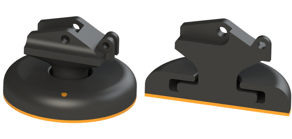
The spin feet were designed as a three part assembly, which mated together and were secured with ABS filament pins.
Unfortunately, due to time constraints, we didn’t get a chance to test the spin feet on the robot.
Tail
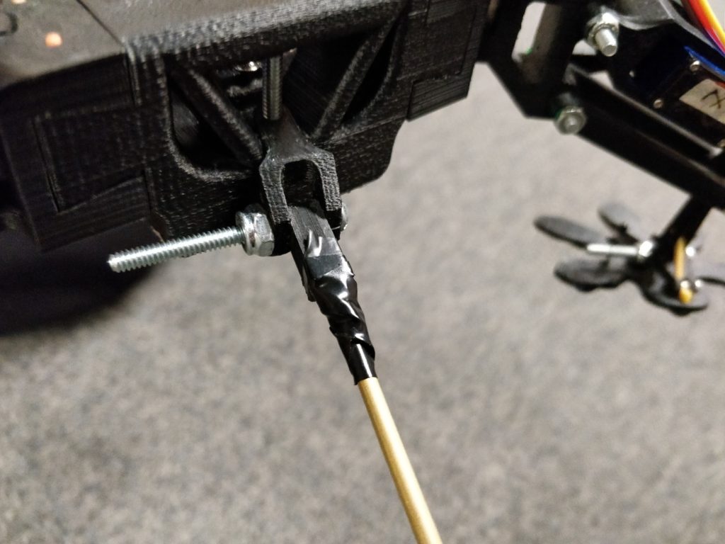
The tail serves to provide a constant contact point, stabilizing the robot as legs lift off the ground during operation. The tail is a slender metal shaft, mounted at the rear of the hips via a tail connection bracket. The tail connection bracket freely swings horizontally with respect to the body and the tail shaft vertical angle can be adjusted with respect to the bracket.
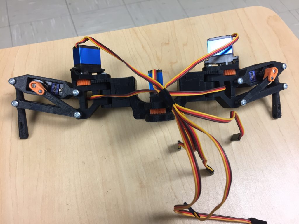
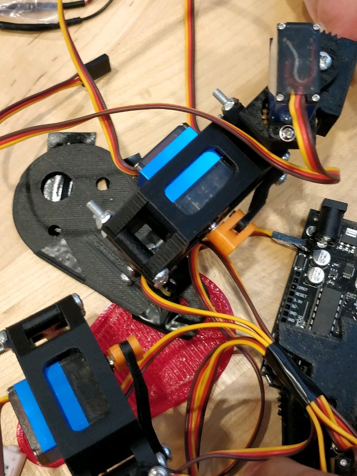
Wiring
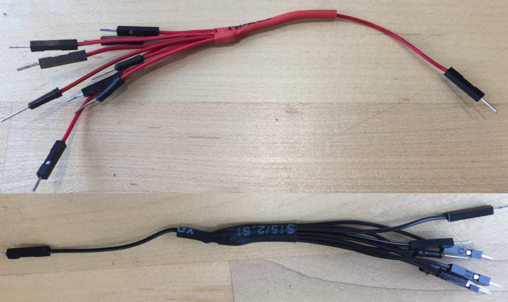
To avoid the added weight and bulk of a breadboard all electrical components were connected exclusively with wire. The ground and Vin of all the servos were connected to the battery using 10:1 and 9:1 wire harnesses, respectively with many wires (one each) going out to each servo and one going to the battery. The 10th ground wire connects to the Arduino to unify the system grounds.
Final Mass and Dimensions
Body Length = 16 cm
Total Distance Needed = 35 * 16 = 560 cm
Total Body Mass = 545.5g
Final Gait
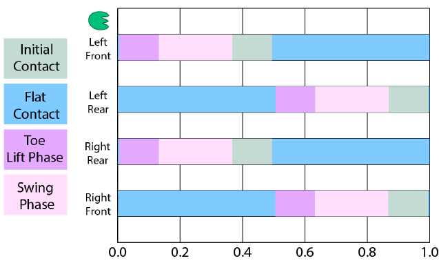
The gait of the robot resembles a the gait of a gecko or of an alligator. The robot always maintains at least three points of contact while in motion. The gait chart describes the gait of each leg of the robot. The robot walks in alternating steps, such that opposing legs (left front and right rear, or right front and left rear) are always in the same contacting position. Only one set of alternate legs are ever in the swing phase at once. Both before and after the swing phase, all four feet contact the ground. As one set of legs is lifted and swept forwards to reach for the next step, the set of legs with feet contacting the ground sweep backwards to drive the robot forwards. This motion alternates between opposing foot sets to maintain a fluid motion.
In order to maintain balance during this gate, the robot uses wide feet and a tail that is always is in contact with the ground. The center of mass of the robot lies between the two feet contacting the ground when they are at their neutral position (perpendicular to the body) in order to maintain the robot’s balance. Once the robot reaches forward with its legs to take a step, the center of mass shifts behind the region of stability between its ground contacting feet. The tail then provides an extra contact point behind the robot to maintain stability while in motion.
While the initial implementation of an undulating motion proved to be very helpful for optimizing the robot’s speed, its implementation added a lot of instability and inconsistency to the gait orientation. Additionally, the servo responsible for undulation struggled to fully rotate the body, particularly on carpeted terrain.
The final gait time is approximately 1 second.
Performance
Hard Floor
The robot walked its full distance on smooth floor perfectly straight. The tape on the floor at the start of the video is the starting line and the tape line at the end of the video (faintly labeled 2) is its finish line – the 2nd to last tape line (there is a 1-second delay between when the robot started and when the video starts.)
Carpeted Floor
The robot walked its full distance on carpet nearly perfectly straight. The tape on the floor at the start of the video is the starting line and the tape line at the end of the video (faintly labeled 2) is its finish line – the 2nd to last tape line.
Other Trials
The team performed a number of trials of the robot on both floor conditions. Videos of some of these trials are included here.
https://youtu.be/0ahUmOzyp9I
CAD & Photos
For a complete compendium of CAD files, renders, and photos (including work in progress CAD/photos, partial renders, specific part/component/subassembly details, and overall project evolution) please see this link.
Imported CAD Models
9V Battery Model: https://grabcad.com/library/9v-battery-1
Sensor Model: https://grabcad.com/library/motion-gyroscope-accelerometer-gy-801-1
Arduino Uno Model: https://grabcad.com/library/arduino-uno-24
Micro Servo Model: https://grabcad.com/library/servo-hxt900-micro