Table of Contents
Introduction
As part of my Planetary Robotics course (ENAE788x) at the University of Maryland, I worked as a team with three other students to design a lunar rover with specific performance and weight parameters. I would be remiss in this writeup if I did not recognize the contributions of my team: Justin Albrecht, Prateek Bhargava, and Sayani Roy, without whom this project would not have been possible. They each deserve equal credit for the ideation, evolution, and progression of this project. I’d also like to thank Dr. David Akin for his guidance and support throughout this project. This writeup walks through the project requirements and constraints as well as the details of the design we created through a semester of work and iteration.
Project Description
The purpose of this project (as described in Dr. Akin’s lecture) was to design a BioBot rover to accompany two astronauts on a lunar mission. The BioBot concept shifts the life support payload from the astronauts’ backs (as a backpack) to an external rover which follows the astronaut around. The backpack life support payload raises the astronaut’s center of mass (both upwards and backwards), which decreases their standing/walking stability and adds exhausting weight to an already cumbersome extravehicular activity (EVA) suit. By relocating the life support equipment to an external rover, the astronaut is freed to move with greater ease.
We needed to perform a detailed design of a BioBot rover, emphasizing mobility systems, chassis systems (e.g., wheels, steering, suspension. . . ), support systems (e.g., energy storage), navigation and guidance system (e.g., sensors, algorithms…). The system must be designed for the Moon, then evaluated for Mars and conversion to an Earth analogue rover.
Mission Parameters and Assumptions
The rover is part of a medium length lunar exploration mission. It’s assumed that there is a lunar habitat (hereafter “Hab”) where the astronauts live and stay during this mission. We assume the Hab is well stocked with resources (oxygen, food, electricity, etc) and the rover therefore only needs to carry sufficient supplies for an 8 hour sortie. The mission includes two EVA crew members and two rovers. In the normal use case, each rover follows one astronaut, and can operate autonomously or be driven with the astronaut on board. For safety and redundancy, each rover must be able to accommodate a second astronaut.
Project Requirements
The following performance requirements established at the start of the project served to bound and guide all of our designs.
The rover must be capable of a maximum operating speed of at least 4 m/sec on level, flat terrain. It must be able to accommodate a 0.3 meter obstacle at minimal velocity, a 0.1 m obstacle at a velocity of 2.5 m/sec, and/or a 20° slope in any direction at a speed of at least 1 m/sec, including the ability to start and stop. A nominal sortie has a range of 54 km at an average speed of 2.5 m/sec.
The rover must be capable of carrying one 170 kg EVA crew and 80 kg of assorted payload (modeled as a 0.25 m box). The rover must also be capable of carrying a second 170 kg EVA crew in a contingency situation. The design should incorporate roll-over protection for the crew and all required ingress/egress aids and crew restraints.
A nominal sortie shall be at least eight hours long. Two rovers must be launched on a single CLPS lander; A single rover shall have a mass ≤250 kg. The rover(s) must be capable of operating indefinitely without crew present; it must be capable of being controlled directly, remotely, or operate autonomously. It must be capable of following an astronaut, astronaut’s path, or autonomous path planning between waypoints, and capable of operating during any portion of the lunar day/night cycle and at any latitude.
Final Design – Intro
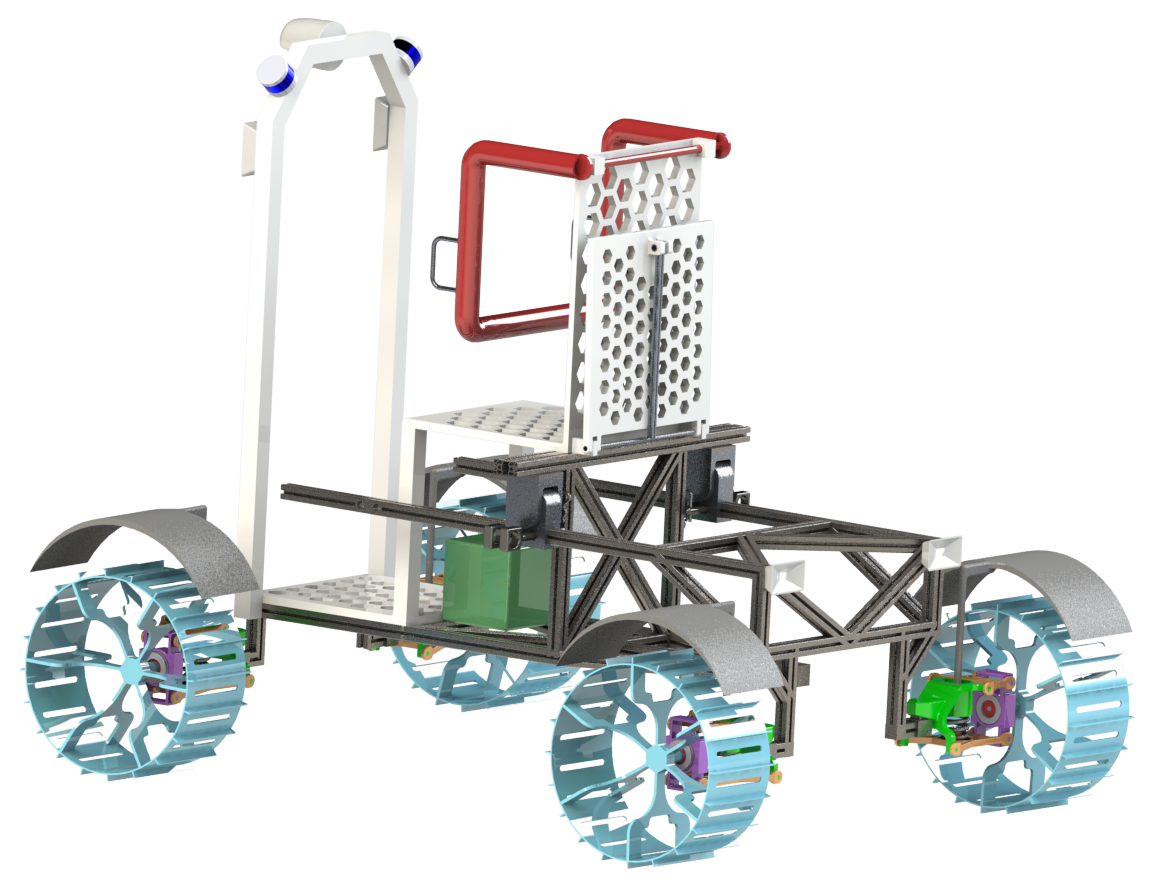
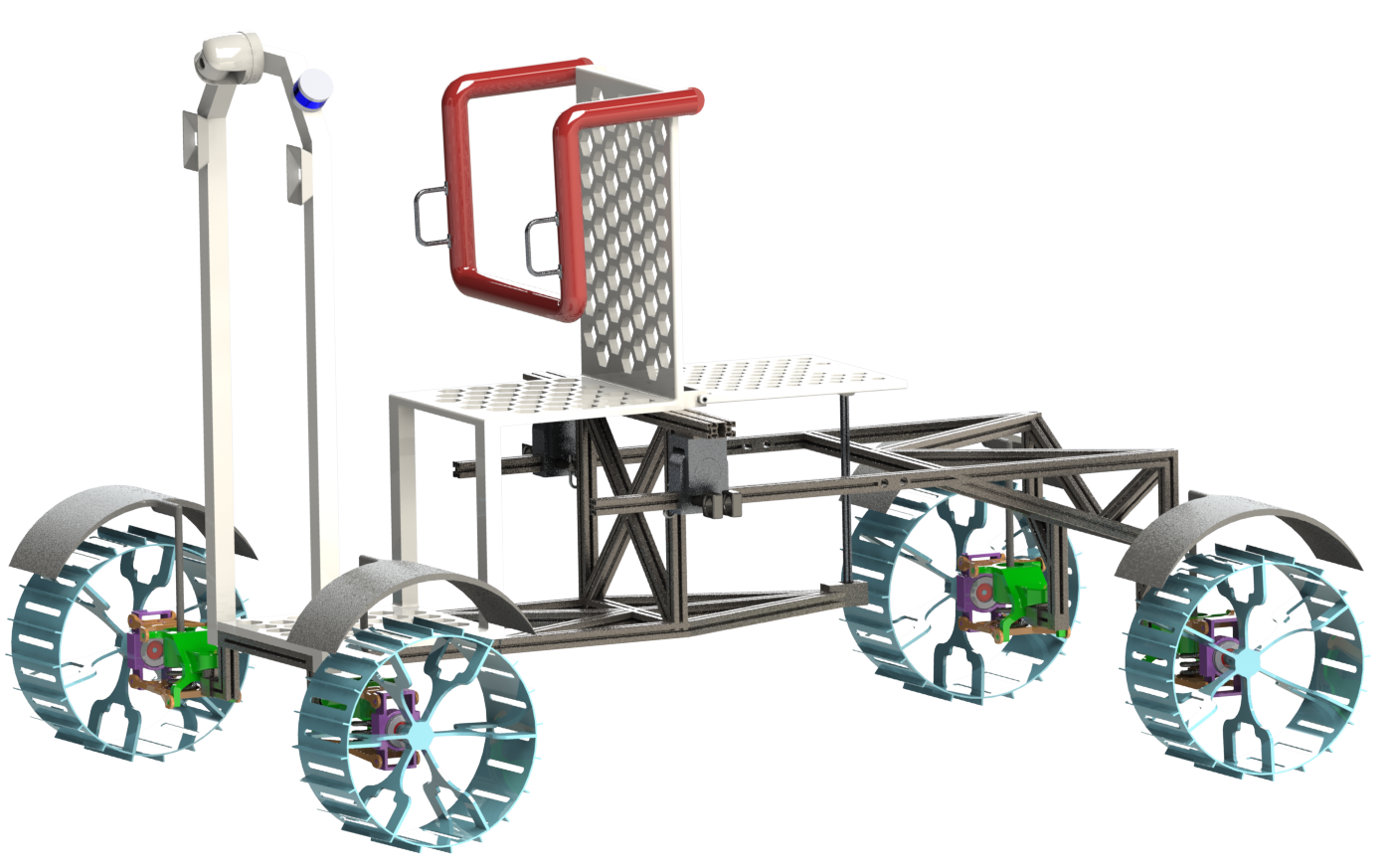
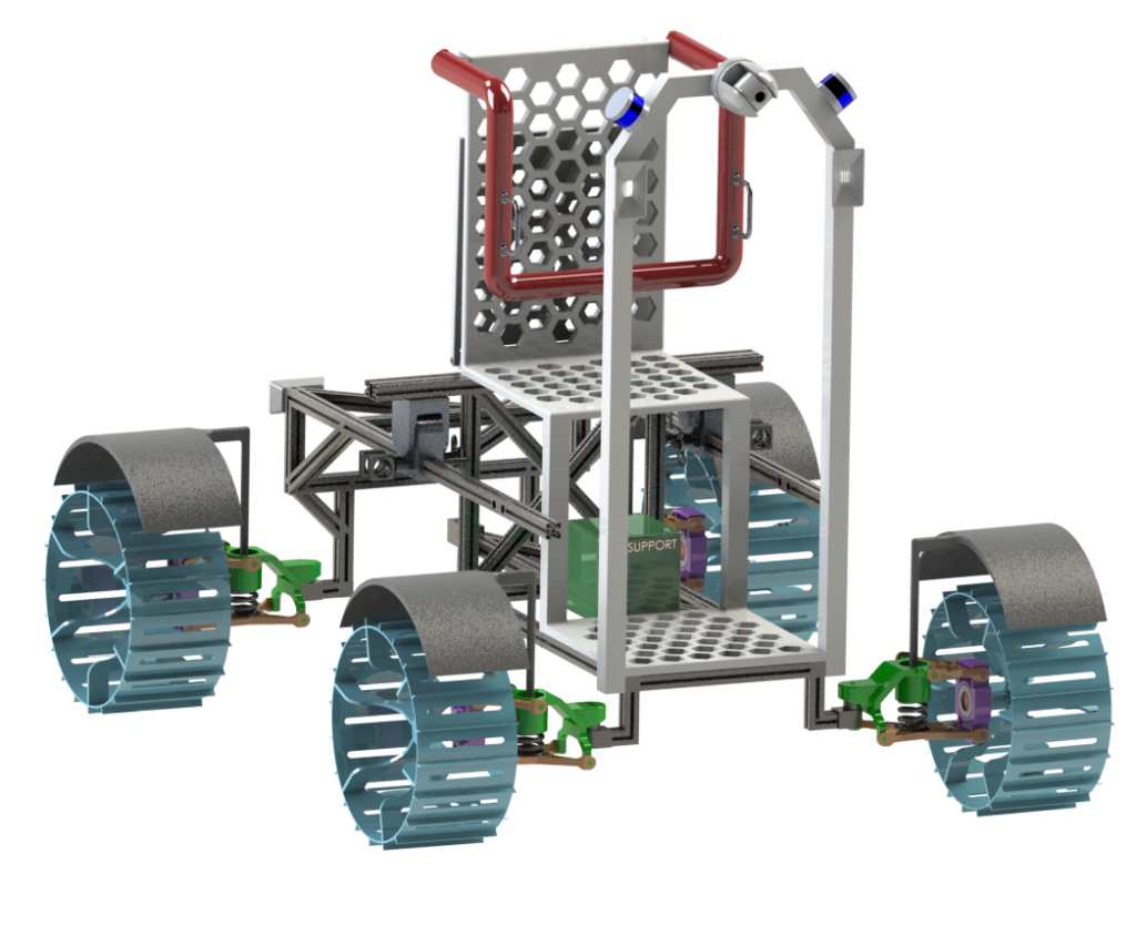
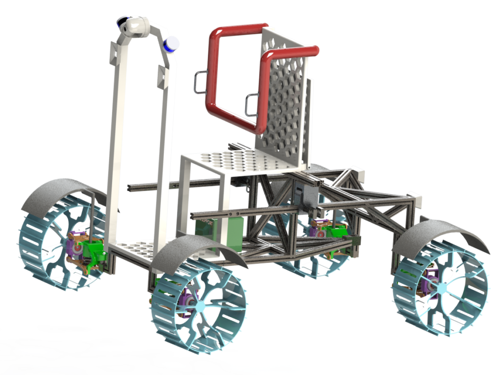
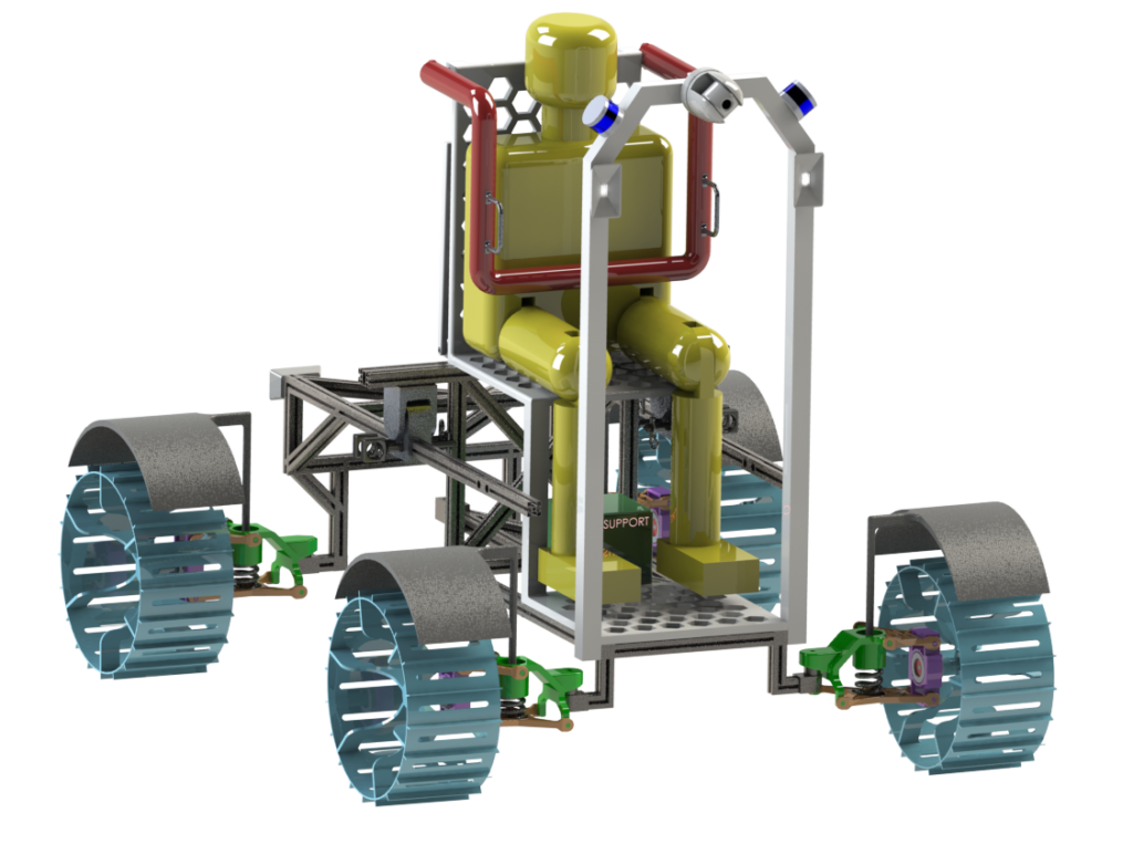
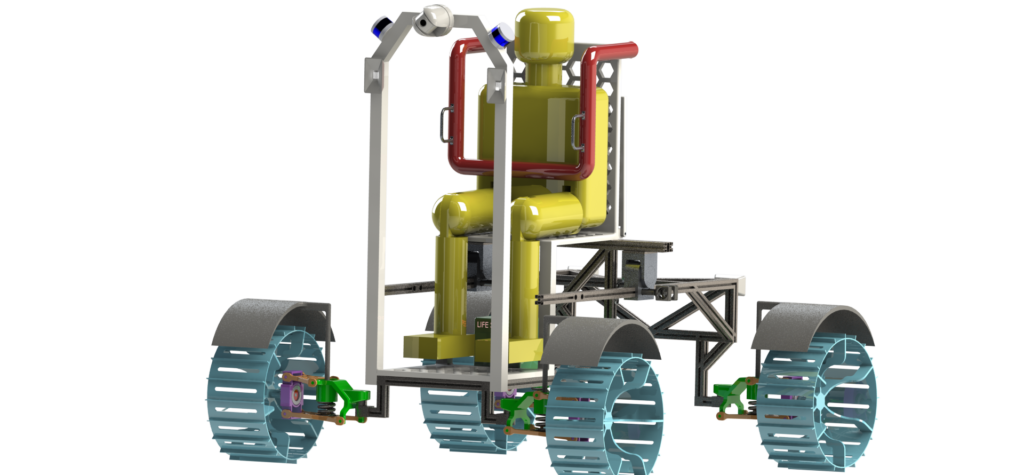
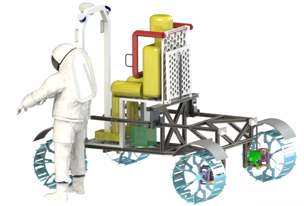
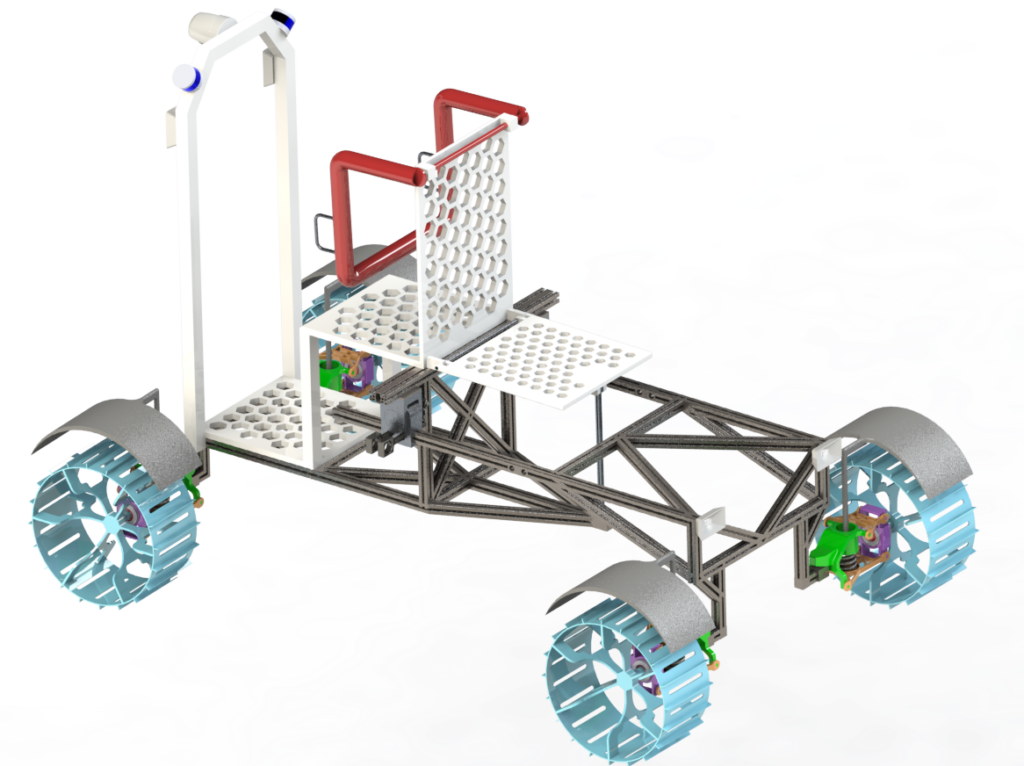
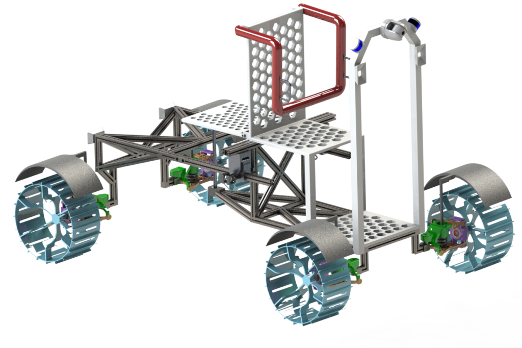
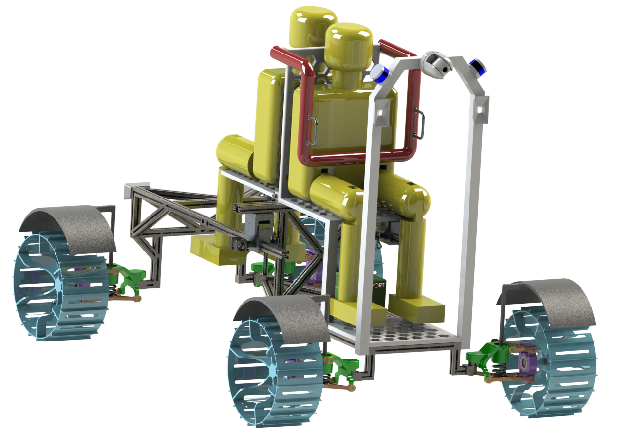
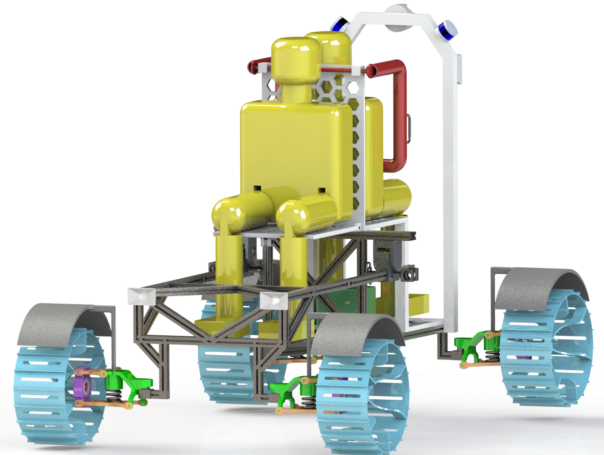
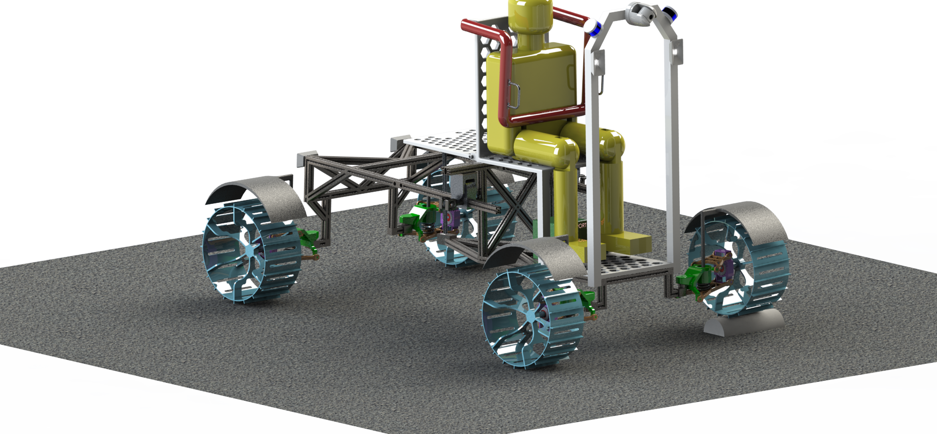
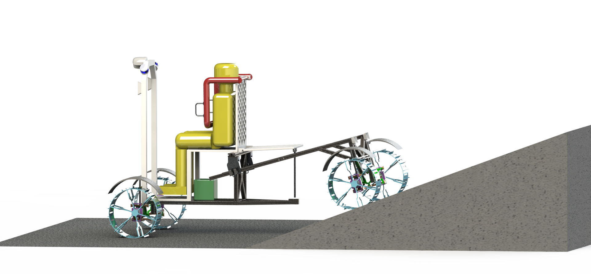
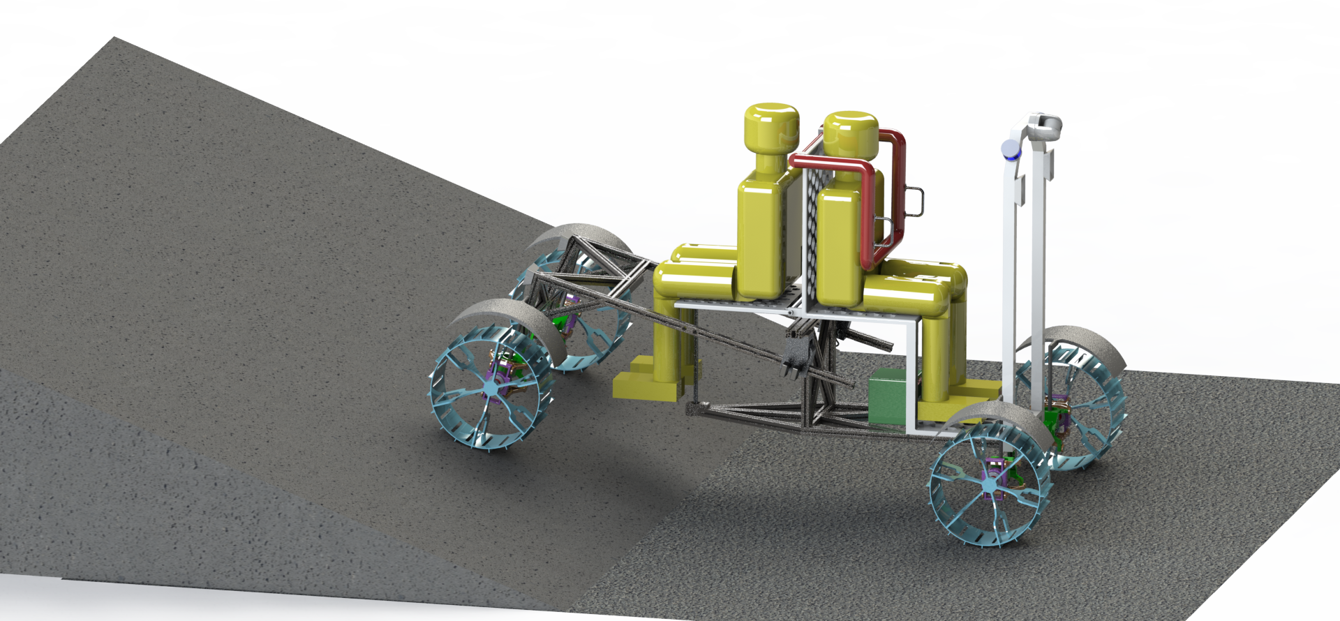
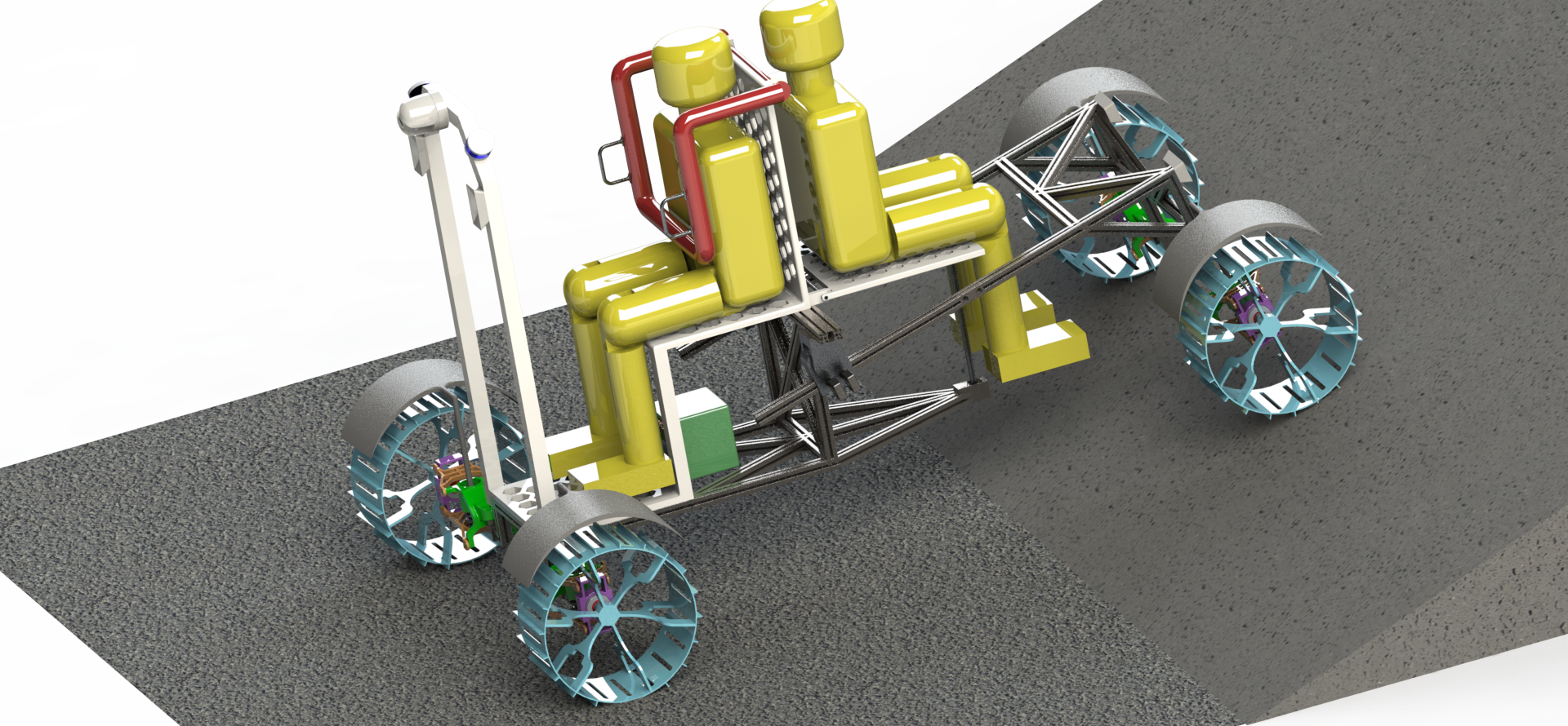
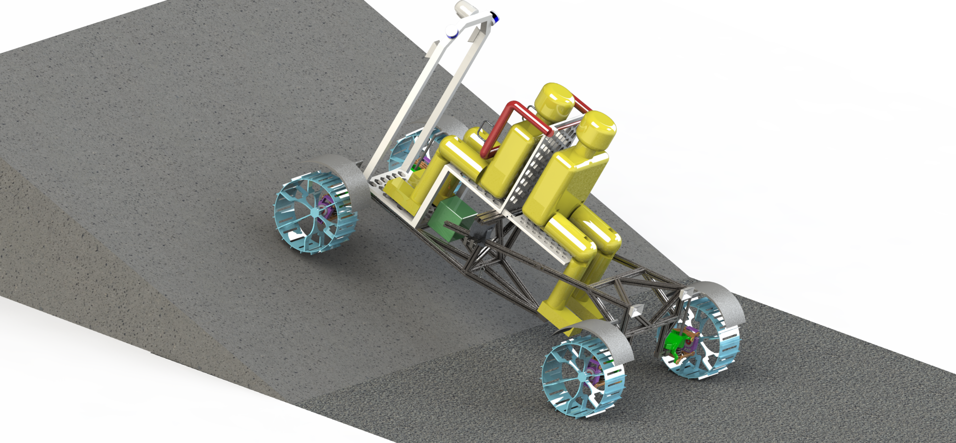
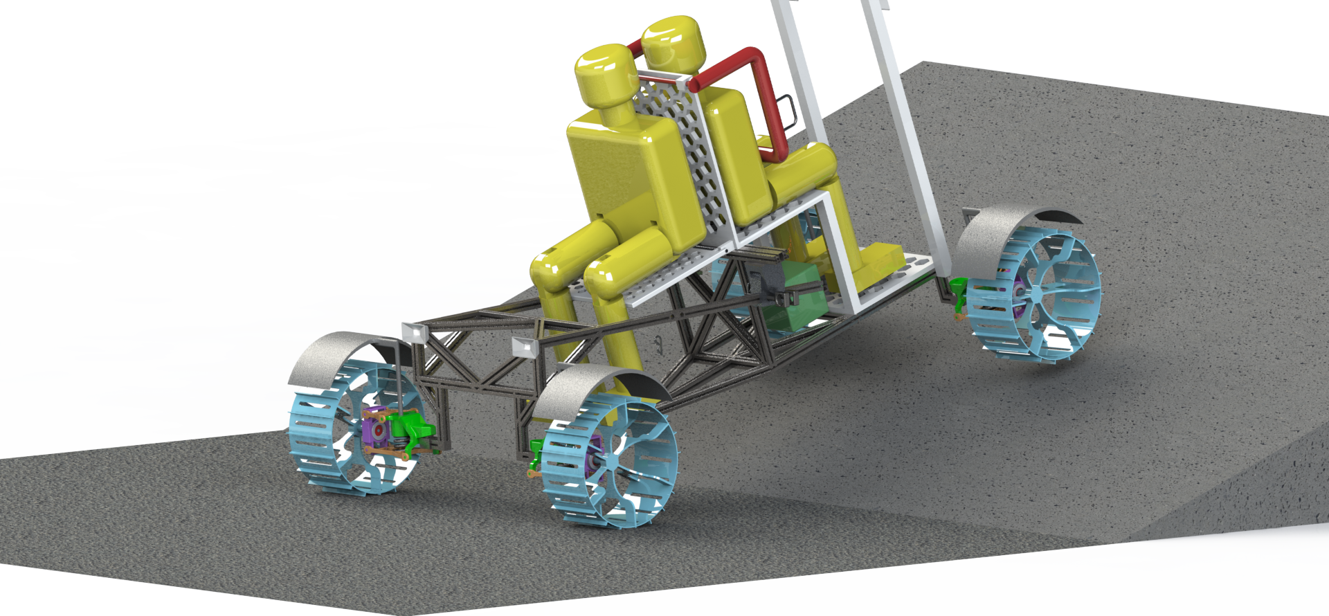
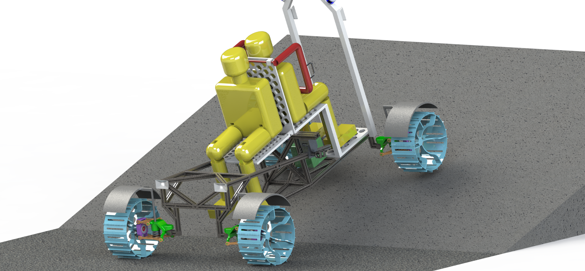
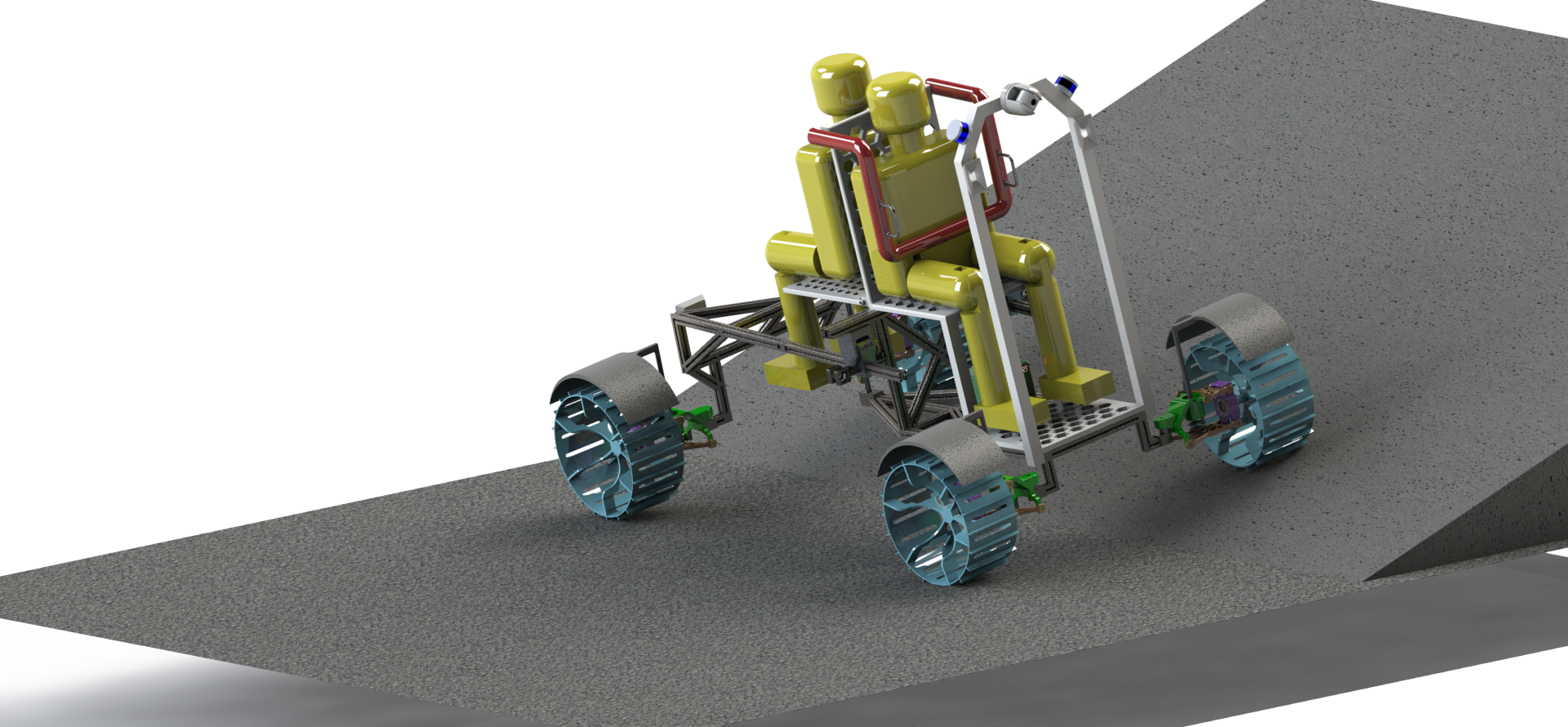
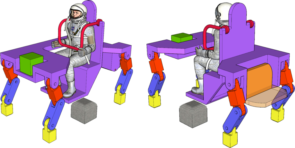
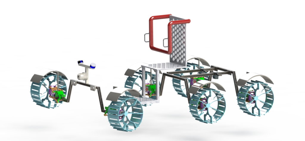
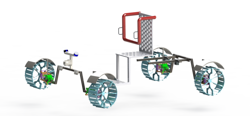
To understand all our final analyses, it’s helpful first to have a cursory understanding of the final design. The final rover is a 4 wheeled vehicle with two chassis. The front chassis is fixed to the seat. The rear chassis attaches to the front chassis via a sliding pivot mechanism. The sliding portion allows the total chassis length to extend to better accommodate a second astronaut, while the pivot mechanism permits the two chassis halves to not be coplanar (such as when entering or exiting a hill). Take a look at the two rendered views below (click on the image to see it larger). The front of the rover faces the same direction as the front seat (with the red restraint). You’ll see references to the extended and non-extended (or “unextended”) cases throughout the rest of this page.

Rover in Unextended Configuration 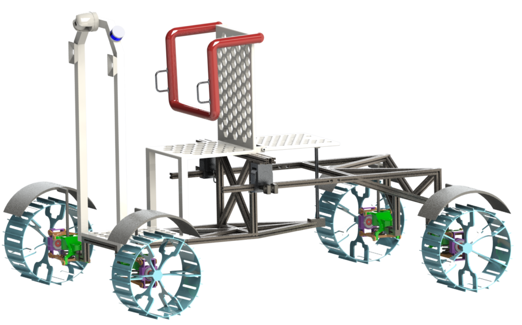
Rover in Extended Configuration
Terramechanics
Terramechanics is the study of how wheels interact with soil.
From the Terramechanics lectures [1] [2] [3] and the equations given below, we performed trade studies between rovers with 4 wheels and 6 wheels to analyze and deduced the width, diameter of our rover for a positive drawbar pull. See our analysis in “terramechanics.mlx” on the Github.
Soil Properties
$$ \text{Modulus of Cohesion of Soil Deformation} = k_c = 1400 \frac{N}{m^2} $$
$$\text{Modulus of Fiction of Soil Deformation} = k_\phi = 820000 \frac{N}{m^3} $$
$$\text{Soil heuristic parameter} = n = 1$$
$$\text{Angle of internal resistance of soil} = \phi = 0.6109$$
$$\text{Density of soil} = \gamma = 2472 \frac{N}{m^3}$$
$$\text{Soil cohesion} = c = 170 \frac{N}{m^2}$$
$$\text{Shear deformation modulus} = K_{shear} = 0.178 m$$
Other Values
$$\text{Mass of Astronaut} = m_a = 170kg$$
$$\text{Mass of Payload} = m_p = 80kg$$
$$\text{Mass of vehicle} = m_v = 250 kg $$
$$\text{Total mass} = 2m_a+m_p+mv = 670kg$$
$$\text{Gravity} = g = 1.62 \frac{m}{s^2}$$
$$\text{Total Vehicle Weight} = W_{tot} = \frac{m_{tot}g}{N_w} = 1085 N$$
$$\text{Number of wheels} = N_w = 4$$
$$\text{Weight on each wheel (assume equally distributed)} = W_w =\frac{W_{tot}}{N_w} = 271N$$
Compression Resistance
$$R_c = \left(\frac{k_c+bk_\phi}{n+1}\right) z^{n+1}$$
$$z = \left(\frac{3}{3-n}\frac{W_w}{(k_c+bk_\phi)\sqrt{D}}\right)^{\frac{2}{2n+1}}$$
Bulldozing Resistance
\begin{equation}
R_b = \frac{b\sin(\alpha+\phi)}{2\sin\alpha\cos\phi}(2zcK_c+\gamma z^2K_\gamma) + \frac{l^3_o \, \gamma}{3}\left(\frac{\pi}{2}-\phi\right) + cl^2_o\left[1+\tan\left(\frac{\pi}{4}+ \frac{\phi}{2}\right)\right]
\end{equation}
$$\alpha = \text{angle of attack of wheel in soil} = \cos^{-1} \left(1-\frac{2z}{D} \right)$$
$$K_c = \text{Cohesive modulus of soil deformation} = (N_c – \tan\phi)\cos^2\phi$$
$$N_q = \frac{\exp \left[\left(\frac{3\pi}{2}-\phi \right)\tan\phi \right]}{2\cos^2 \left(\frac{\pi}{4} + \frac{\phi}{2} \right)}$$
$$N_c = \frac{N_q -1}{\tan\phi}$$
$$K_\gamma = \left[ \frac{2N_\gamma}{\tan\phi} + 1\right] \cos^2\phi$$
$$N_\gamma = \frac{2(N_q+1)\tan\phi}{1+0.4\sin(4\phi)}$$
$$l_o = z\tan^2 \left( \frac{\pi}{4} – \frac{\phi}{2} \right)$$
Gravitation Resistance
\begin{equation}
R_g = W_v \sin\theta_{slope}
\end{equation}
Rolling Resistance
$$c_f (\text{coefficient of friction}) = 0.05$$
\begin{equation}
R_r = W_{tot} \, c_f
\end{equation}
Tractive Force for Smooth Wheel
$$H_s = (blc_0+W_w\tan\phi)\left[1-\frac{K}{sl} \left(1-e^{\frac{-sl}{K}}\right) \right]$$
$$l = \text{length of contact patch} = \frac{D}{2}\cos^{-1} \left(1-\frac{2z}{D}\right)$$
Tractive Force for Wheels with Grousers
$$N_g = \frac{\pi D}{N_{tot}l}$$
\begin{equation}
H_g = \left[blc_0 \left(1+ \frac{2h}{b} \right)N_g + W_w \tan\phi \left(1+0.64\frac{h}{b} \: \tan^{-1} \frac{b}{h} \right) \right] \left[1-\frac{K_{shear}}{sl} \left(1-e^{\frac{-sl}{K_{shear}}} \right) \right]
\end{equation}
Drawbar pull
\begin{equation}
DP =N_w H – (N_wR_c + N_wR_b + R_g + R_r)
\end{equation}
Flat 
20 deg Slope
From the above trade studies performed between 4 wheels and 6 wheels (additional trade studies depicted in the presentation) for diameter, width of wheels against drawbar pull, number of grousers and height of grousers; we have have chosen the following values:
- Number of wheels (N) = 4
- Diameter of wheel (d) = 0.6m
- Width of wheel (w) = 0.3m
- Number of grousers = 20
- Height of grousers = 2 cm
Stability
For our selected rover with 4 wheels we find its stability on both flat terrain and a slope of 20 degrees in both the cases: Non-Extended and Extended. The system will remain on the ground for slope that results in a positive normal force on every wheel. The zero normal force condition is when the wheels lift off the ground.
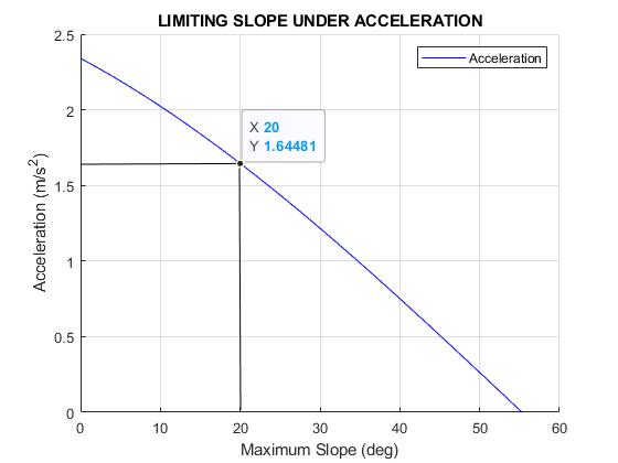
Acceleration 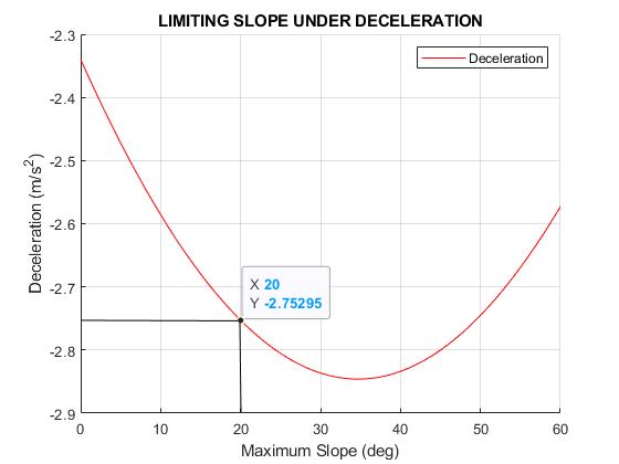
Deceleration
Flat Terrain 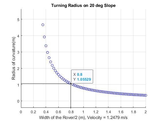
20 degree slope
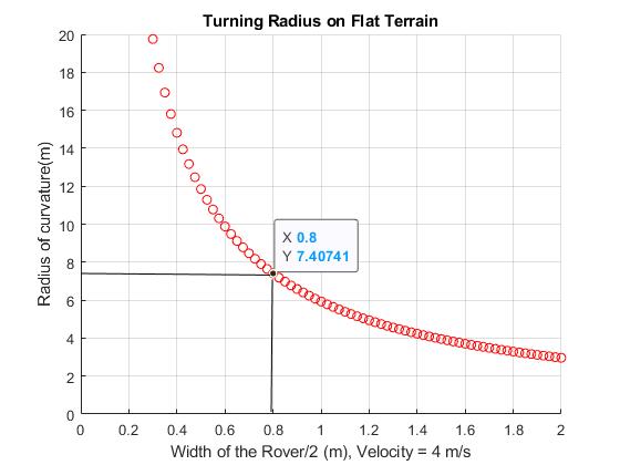
Steering
The front two wheels are direct steered, each with steering motor. The rear two wheels are fixed to the chassis. You can view a video of the front wheels moving through their range of motion below.
Please see Slide 153 for additional graphs related to steering. From the values obtained for the radius of curvature of the rover in Non-Extended and Extended states for the cases: Flat terrain and slope of 20 degrees, we obtain the values for the steering angle required by each wheel (outer and inner) while undergoing a turn. This is depicted in the figures below:
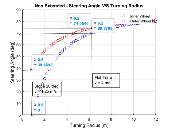
Non-extended 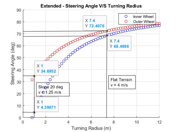
Extended
Driving
There are a few different ways we devised for the astronauts to control and drive the rover. Fortunately, both the automobile and gaming industries have developed many different types of controllers.
AR Arc Targets
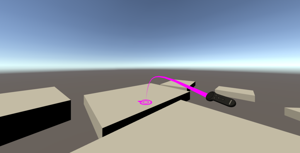
We envision that the astronauts’ EVA suits could be equipped with a Virtual Reality (VR) style remote and an Augmented Reality (AR) Heads Up Display (HUD) inside their visor. In virtual reality applications, a popular method of locomotion is teleportation (walking tends to quickly cause motion sickness). The player points their controller, which projects a parabolic curve to the landscape, with a target at the end. When the player has the target positioned where they want it, they hit another button and are teleported to that spot. We obviously don’t have teleportation capabilities for this project, but we like this method of selecting a destination.
The rover is equipped with sufficient LiDAR and cameras to produce a detailed model of the nearby landscape, which could be viewable by the astronaut via their HUD. In this transportation method, the astronaut would use their suit control and HUD to point to a target destination in a similar way, and the rover would autonomously path plan and drive to that location. This allows the astronaut easy control over the destination and leaves all control over the terrain-traversing details to the rover. We believe method works well regardless of whether or not the astronaut is on board. Once the rover has reached the destination, the astronaut can select a new, further destination and have the rover drive there.
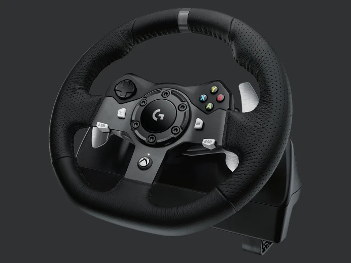
Traditional Steering Wheel
When the astronaut is on board the rover, the simplest way to drive the car-like vehicle is with a traditional steering wheel. The Apollo LRV also used a steering wheel for control. EVA suits are stiff, and we weren’t sure how much flexibility the ankles would have to delicately control an accelerator and brake pedal. Instead, we’ve equipped the rover with a gaming steering wheel which has paddles behind the wheel to control the throttle. The wheel is equipped with additional buttons for other system control options (including an autonomous “Return to Hab” feature). Like other pieces of this design, this steering wheel is an Earth analog, and some modifications would need to be made for it to be suitable to use on the moon. While remote steering may be impractical(made easier with a live camera view in the HUD), the steering wheel is wireless and can therefore be operated by an astronaut not onboard the rover.
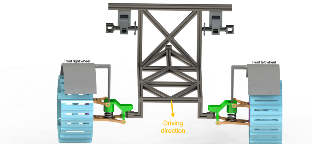
Suspension
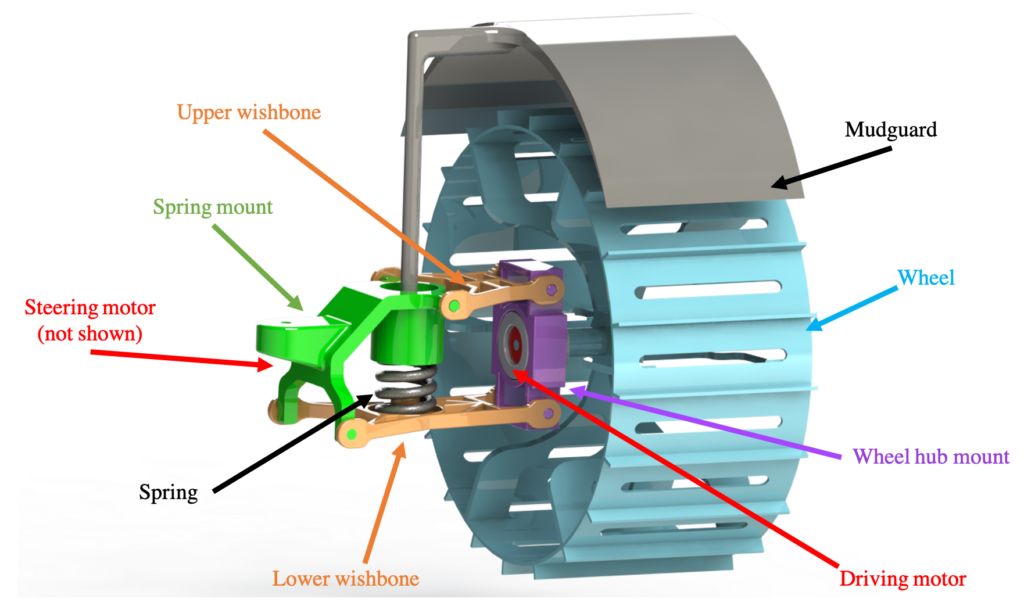
The suspension system we have chosen is known as a double wish-bone suspension. This type of suspension is often used in commercial vehicles. The system has a main bracket that connects either to the steering motors in the case of the front wheels or directly to the chassis for the rear wheels. From this bracket there is a top wishbone and bottom wishbone each mounted on pivots. A spring lies between the wishbones that returns the system back to a neutral position. The other two ends of the wishbone connect to our drive motor bracket which it turn connects to the wheel. Figure 7 shows the major components. The main benefit of this type of suspension is that there is very little wheel camber relative to wheel motion. In other words the wheel should stay mostly perpendicular to the chassis throughout the range of motion. See a video of our suspension in action below:
Independent Suspension Calculations
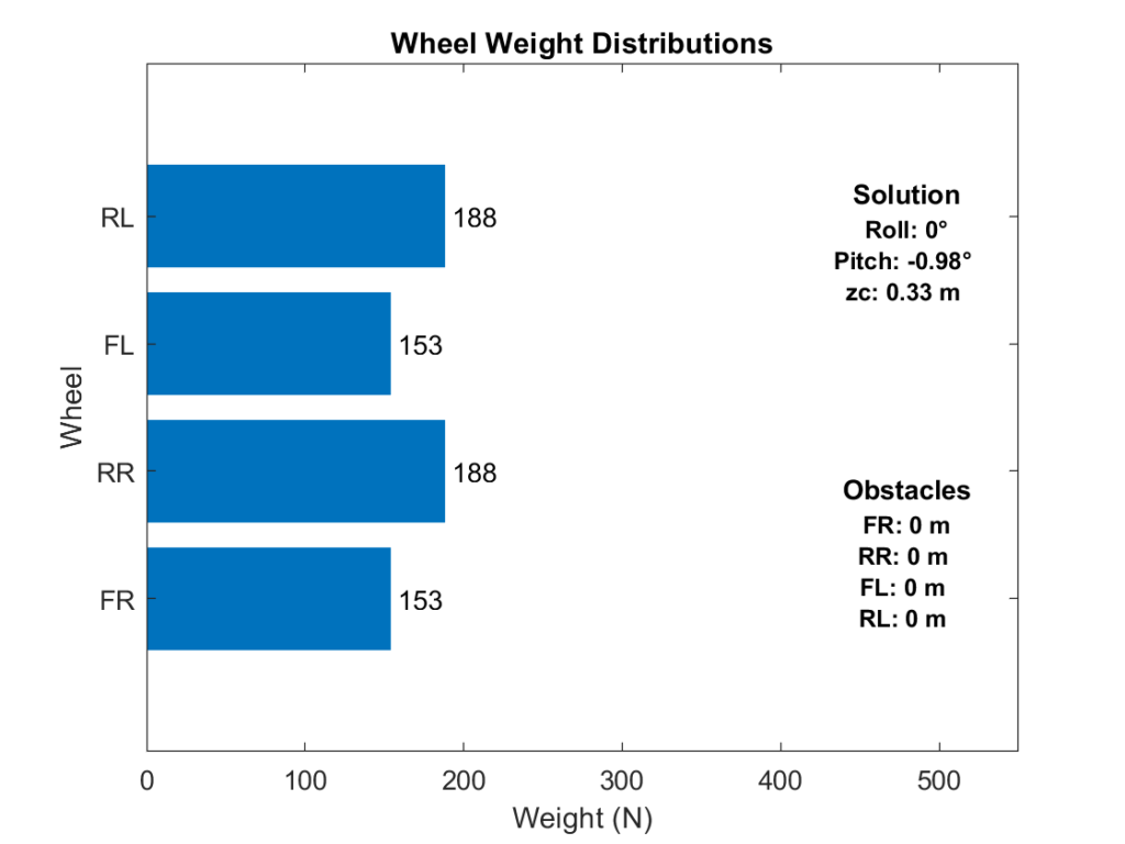
Following the steps for independent suspension calculations [4], we can determine the force on each of the wheels. The error for the three constraint equations below are minimized to find the roll, pitch, and z offset of the rover. These constraint equations ensure that the error for the sum of the forces and moments are close to zero. These values can be applied to our rover transforms to find the height of each wheel offset from the base frame of the rover. For our calculations we set the COM offsets for both the standard configuration and the extended configuration then use MATLAB’s vpa solve to numerically solve the equations.
$$\sum_1^{\text{n wheels}}F_{spr(i)} = W_v$$
$$\sum_1^{\text{n wheels}}F_{spr(i)}x_{w(i)} + W_v x_{cg} = 0$$
$$\sum_1^{\text{n wheels}}F_{spr(i)}y_{w(i)} + W_v y_{cg} = 0$$
The results of the equations on flat ground in both the extended and standard case are shown in the Figures below.
Suspension in unextended configuration 
Suspension in extended configuration

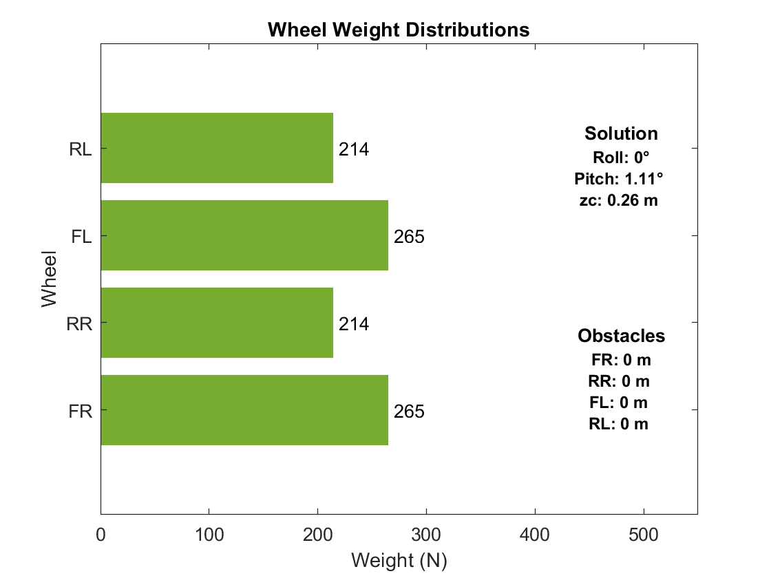
In addition to flat ground, we can explore the results for any arbitrary set of obstacles under any combination of wheels.
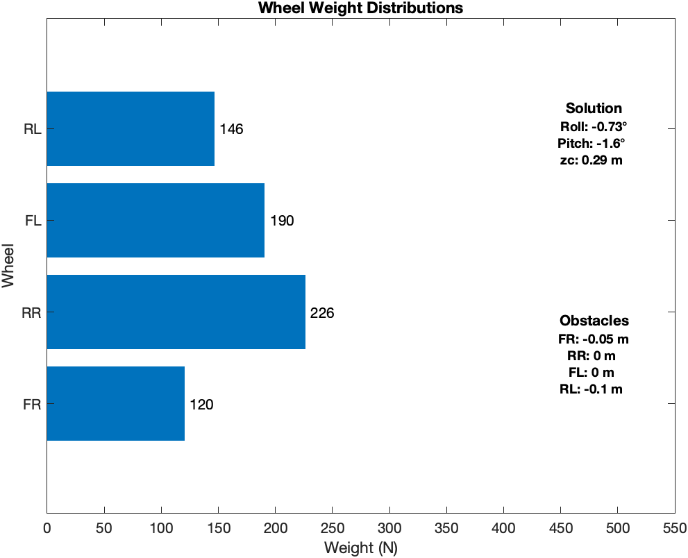
Suspension in unextended configuration 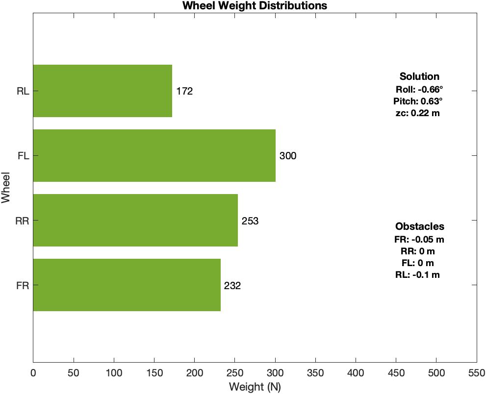
Suspension in extended configuration
You can explore different obstacle configurations in the ‘suspension.mlx‘ file on the Github.
Motors
There are two types of motors required for this rover design – steering motors and driving motors. The motors used were chosen based on the requirements of steering motor and driving motor.
Steering Motor Requirements
Using the turning radius value for non-extended and extended configuration, the power required to steer the rover was calculated. The graphs below shows that the rover requires a steering motor with output power ~ 160 Watts to steer the rover in both the non-extended and extended configuration.
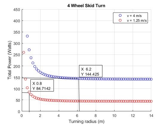
Non-Extended 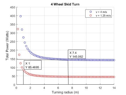
Extended
The power ratio for steering of the rover on both flat terrain and 20 degree slope was also calculated using the values from steering angle calculations.
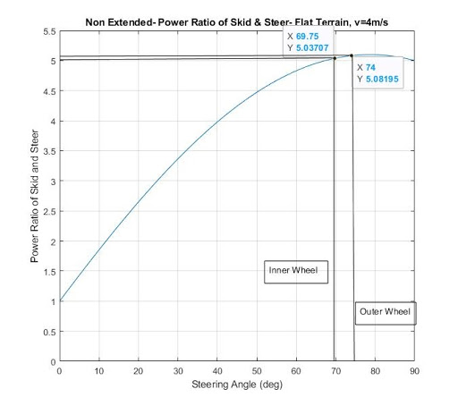
Non-Extended 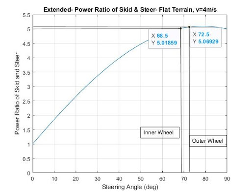
Extended
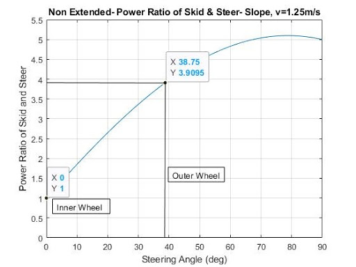
Non-Extended 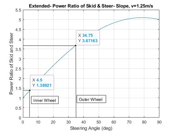
Extended
Driving Motor Requirements
The driving motor needs to have sufficient torque as well as speed so as to turn the wheels. The two graphs below show the speed and torque required for particular gear ratios. We choose a gear ratio of 200 to get the driving motor requirements. The driving motor requires a speed ~4000 RPM to satisfy both the speed conditions and a torque ~ 1 N-m.
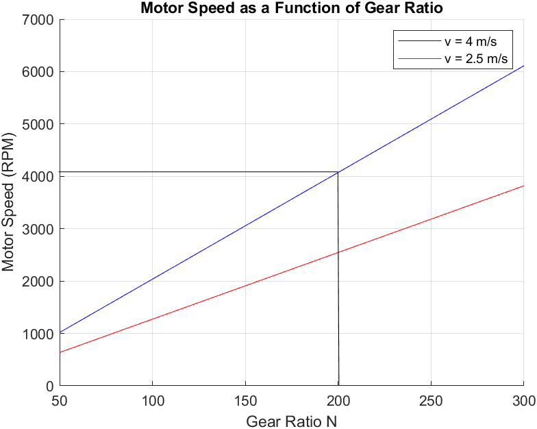
Motor speed (RPM) vs Gear Ratio 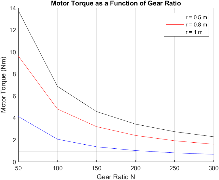
Motor Torque (N-m) vs Gear Ratio
Motor Selection
Brushless DC motors were chosen as they require low maintenance and have long lifespan as well as high efficiency. A motor from the RBE(H) 01212 series was chosen for both driving and steering motor as it satisfies all the power, torque and speed requirements.
Sensors, Perception, and Computing
The rover needs to be operable autonomously, so it needs sufficient proprioceptive and exteroceptive sensors and computational power to understand it’s environment.
Lighting
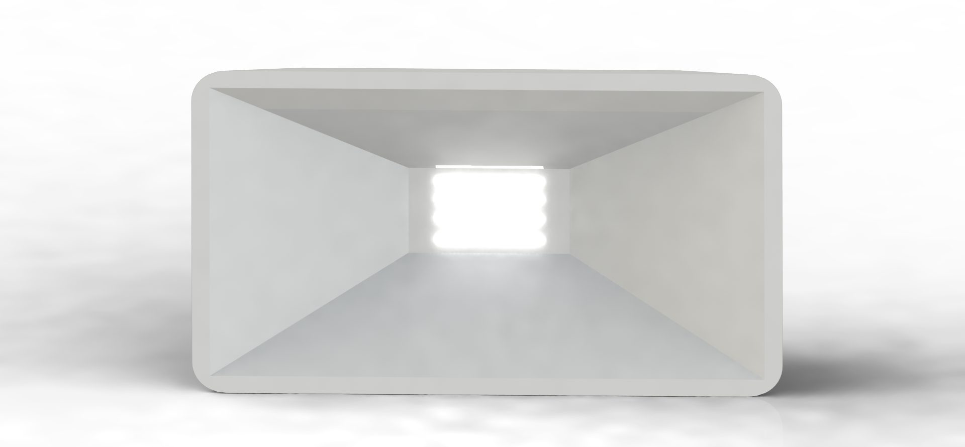
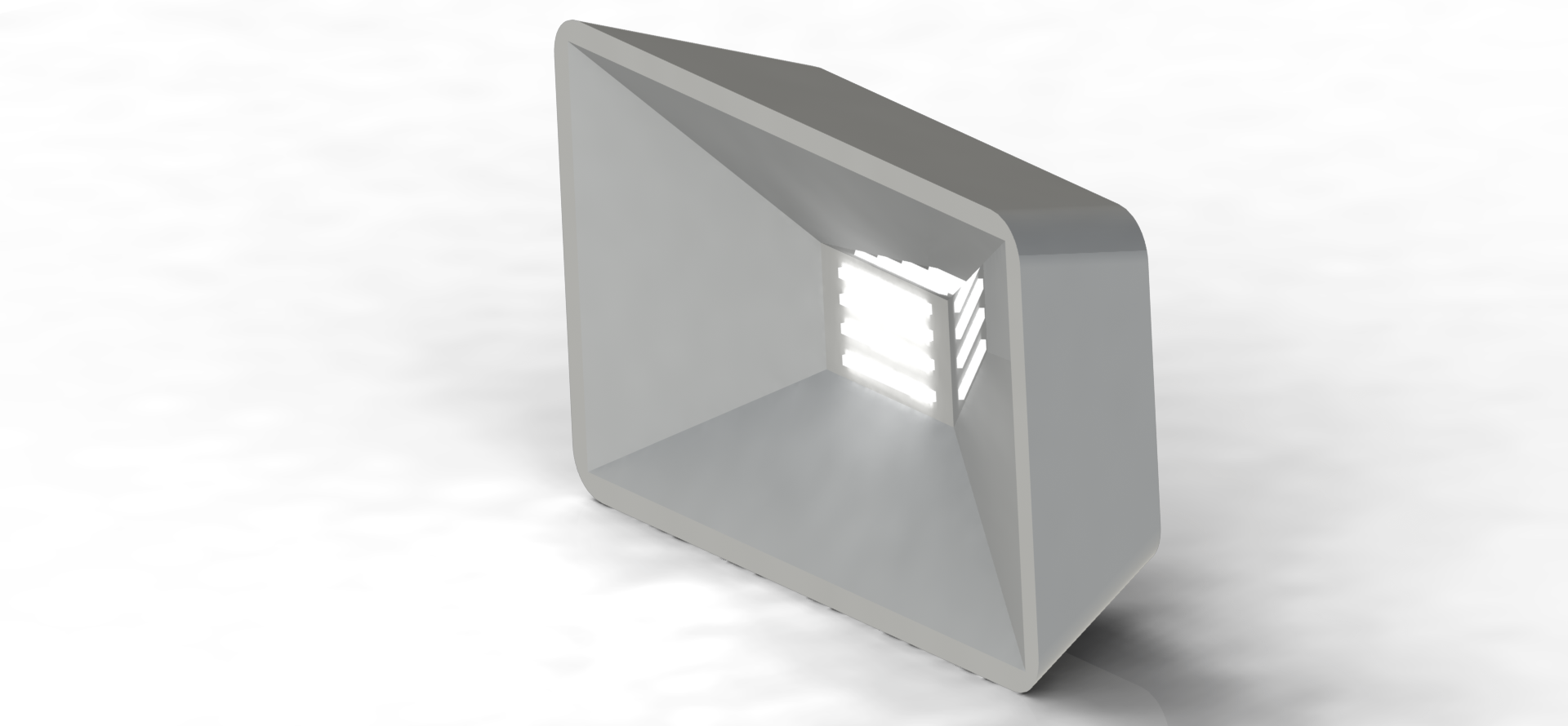
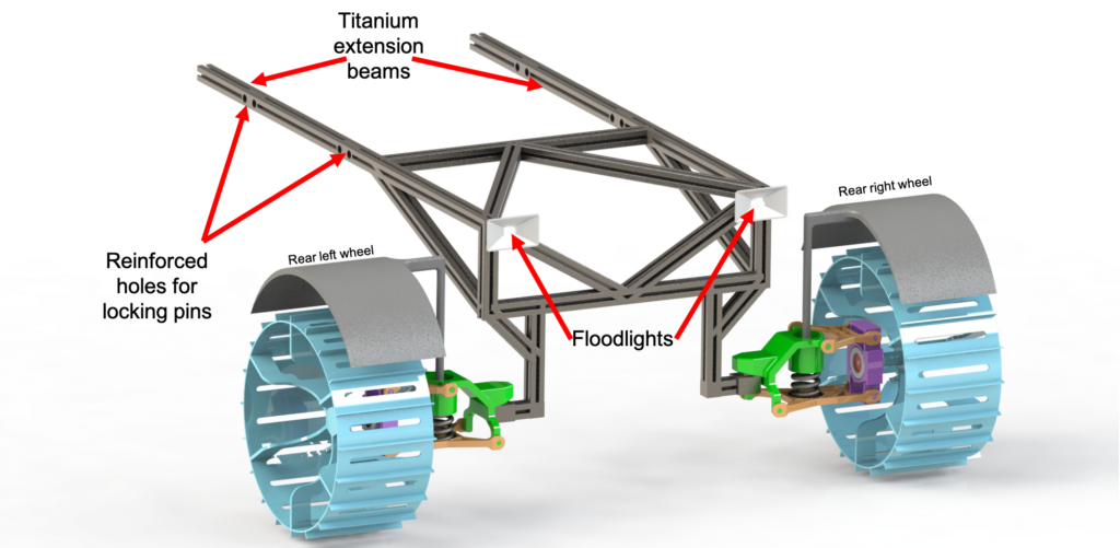
Without an atmosphere to reflect ambient light, the lunar surface is dark and shadowy. Proper illumination will be important for the astronauts to work and for the rover’s vision systems to function in a useful way. We’ve equipped the rover with four 35,000 lumen LED floodlights for illumination. LED floodlights have terrific energy efficiency (especially when compared to incandescent or halogen) and provide excellent brightness for very little weight. By far, most of the weight of the floodlight assembly is the plastic/glass/metal housing, and the LEDs themselves contribute negligibly. Each of the 4 floodlights has a mass of 0.6kg, for a total mass of 2.4kg. Each draws 30W, for a 120W total.
LiDAR
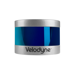
The rover will be equipped with 4 Velodyne Puck LITEs for complete LiDAR coverage. The Puck LITE was chosen (instead of the Ultra Puck or Alpha Puck) for it’s lower weight. The rover is one of just a few vehicles on the moon (as compared to hundreds of vehicles in the immediate vicinity of a car on an Earth highway) and therefore doesn’t need the superior response time or resolution of these higher end pucks. The Puck LITE still provides an impressive 100m range, 30° vertical field of view, and 3cm accuracy [5]. Each puck has a mass of 0.59 kg and requires 8W, for a 2.4 kg total mass and 32W total power.
Cameras
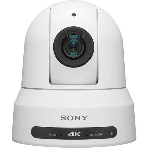
Sony BRC-x400 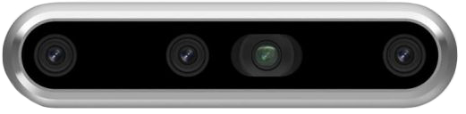
Intel Realsense D455 
Go Pro Max
A comprehensive vision system will be valuable for autonomous rover operation, as well as more detailed science (especially science/op- eration conducted remotely from Earth). Camera quality has improved dramatically since the 1960s, and we can now supplement our rover with a number of very high quality cameras with little financial, power, or weight cost. We’ve selected 7 Earth-analog cameras which (when modified for a space environment) would be excellent for the rover system. We start with two Sony 4K BRC-x400 Pan Tilt Zoom (PTZ) cameras, each weighing 1.8kg and requiring 25W (max). The 3 degrees of freedom in these cameras make them very useful for exploring an environment.
Stereo cameras, in which two cameras side by side can provide binocular depth perception, are useful for both visual perception and depth. These supplement the Velodyne LiDAR pucks’ ability to understand the geometry of the nearby environment, adding both additional information and failure-proofing redundancy into the system. Intel makes several stereo vision cameras, including the RealSense D455, which boasts a depth range from 0.4m to 20m.
The cameras listed above can only look in one direction at once. While there may be some overlap in their potential coverage, it will also be helpful to have a camera with an unobscured 360° view of the surroundings. The GoPro Max is incredibly compact, lightweight, and offers 6K video recording capabilities of the entire environment via two opposing wide angle cameras. The addition of this (or a comparable) camera ensures that the rover will have no blind spots and will be able to operate fully autonomously. This camera may also be useful for remote operation or remote troubleshooting.
To enable the rover to track the astronaut, each astronaut’s EVA suit would be augmented with retro reflectors and fiducial markers (like Apriltags), which would be clearly visible to the cameras. Additional tracking features like ultra wide band triangulation or motion capture bulbs may also be implemented.
Motion Sensors
The rover will have encoders on each wheel as well as several multi-axis inertial measurement units (IMUs) on board to fully understand it’s pose and how it has traveled. These will serve in feedback loops for the driving controllers to help ensure the rover drives to exactly where it intends to go. The exact details of these sensing systems depend tremendously on the detailed specifications of the entire rover as well as the control schema, the later of which is out of scope for this project.
Computing
Autonomous path planning and full utilization of LiDAR + cameras requires non-trivial computing power, certainly more than we’ve sent to the Moon (or Mars) previously. Modern laptops are fairly capable, and it’s possible that a very high end laptop would have sufficient computational power (and speed) to be useful in this scenario. In a slightly larger (and much more power hungry) form factor, a gaming desktop computer with a dedicated GPU, more RAM, and 8+ CPUs is certainly a capable solution to this task. The winning trade-off between electrical power and computational capability would depend on the available power, weight, and needs of the system. We assumed that a high end laptop (minus the screen) would be viable for this project (1kg, 61W).
Communication
The idea of a several 8 hour sorties implies that there will be an established habitat (“Hab”) on the moon prior to the arrival of the rover or astronauts. We assume the Hab is well equipped with sufficient radio equipment to communicate with Earth at an excellent speed and duplex. The rover only needs to be capable of communicating with the Hab, which would then relay any Earth bound communications in that direction. The rover has a specified driving range of 54km. Assuming the astronauts have to be in the Hab at the end of the sortie, the furthest they can drive is 27km (half of 54km out, and the other half back). Modern smart phones communicate wirelessly over a range of cellular data protocols, most of which are fairly long range and high bandwidth. The smart phone requires very little mass or power to engage in these communications. It’s not hard to imagine that a Hab equipped with comparable cell tower technology could communicate with the rover in a similar way, and that the requisite communication apparatus in the rover would be negligibly small in mass and power. We’ll roll these communication mechanisms into the on-board computer.
Power
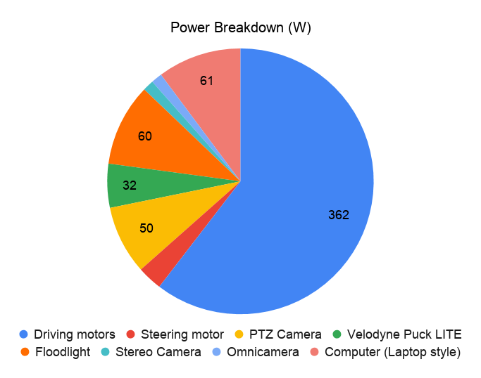
The Hab must be equipped with its own power supply (nuclear or solar, likely). The rover only needs to carry enough power for an 8 hour day of use, and can be recharged overnight by the Hab. The table below shows the power requirements for each powered component of the rover. Power requirements for the sensors/lighting section were taken from the comparable Earth analogs mentioned above.
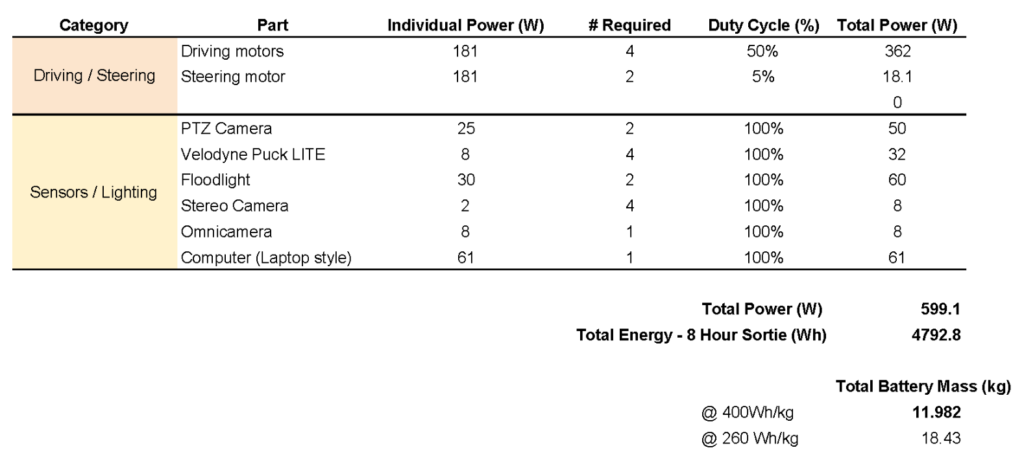
We assume a 50% duty cycle for our driving motors, and a 5% duty cycle for the steering motors. It’s very unlikely that the astronauts would be driving at full speed for their entire 8 hour sortie, and unless they are doing donuts for the whole, it’s unlikely the steering motors will see heavy use. The cameras, lights, and computers, by contrast, will likely be operational continuously for the entire expedition.
We evaluated two Earth analog batteries for the rover. The 260Wh/kg battery density comes from the Tesla Model 3 electric car battery, which is already in production and general use. Tesla has announced they plan to release a 400Wh/kg battery in the next few years. We assume this is an achievable benchmark if NASA were to put sufficient money/energy into further space-rated battery development. We use this more efficient battery for the weight constrained rover.
Mass
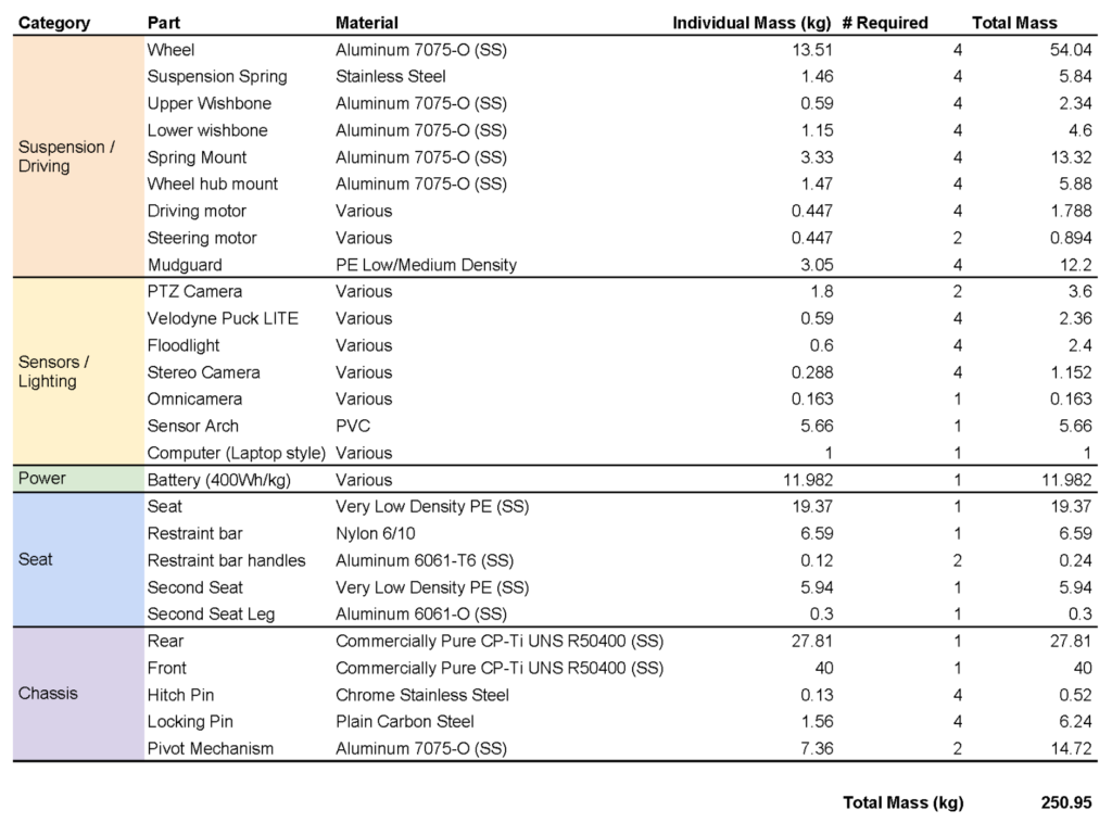
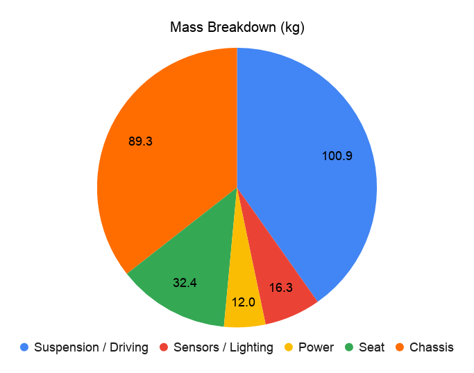
For a better understanding of each of the subassemblies listed in the Mass table, please see the Subassemblies section below. The mass of the sensor/lighting systems come from their Earth analogues, and for the purposes of this project, these serve as a legitimate benchmark estimates for comparable space systems. Most of the aluminum components are modeled with Aluminum 7075, for its greater tensile and shear strength when compared to Aluminum 6061. The plastic and nylon components are modeled with these materials as a placeholder. The extreme temperature range of the moon makes many plastics impractical. The plastic components require little structural strength (especially in the 1/6th gravity of the moon) and should therefore be built with low density (plastic-like) materials. Carbon fiber, with an excellent strength to weight ratio, might be used to replace or reinforce some of these components.
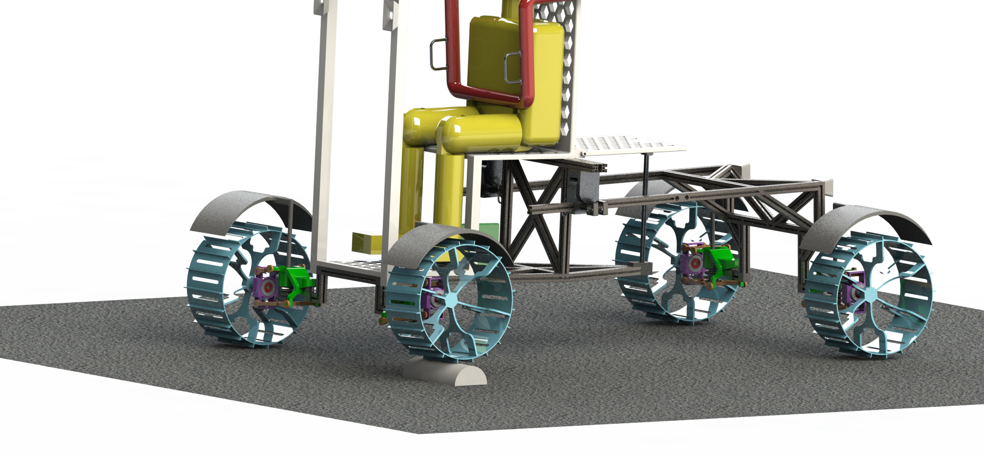
Final Design
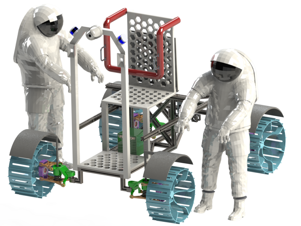
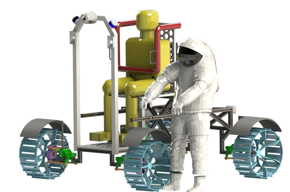
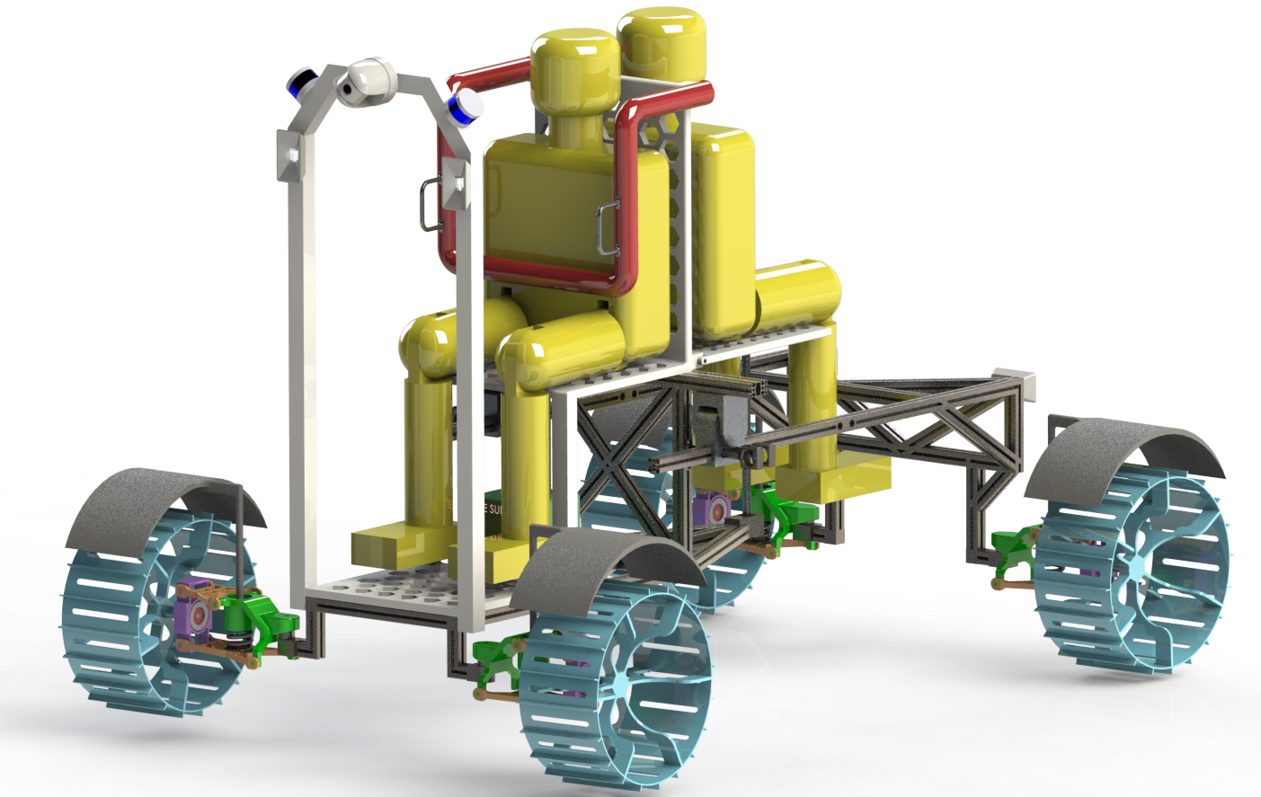
Our final design is the culmination of a semester of design iteration, evolution, and revisited analyses. To better understand how we came to this final concept and the designs we explored along the way, please see the Design Evolution section below. In some the following renders, you’ll see Z2 astronauts and Lego style astronauts. The LEGO trademark is owned by the LEGO Group, which is entirely unaffiliated with this project. We needed vaguely humanoid placeholder astronauts with positionable limbs in the model to get more accurate center of mass positions, and designed these simple yellow blocky astronauts to fulfill this purpose. We’ll refer to them as Lego Astronauts because they (intentionally) bear significant resemblance to LEGO characters.
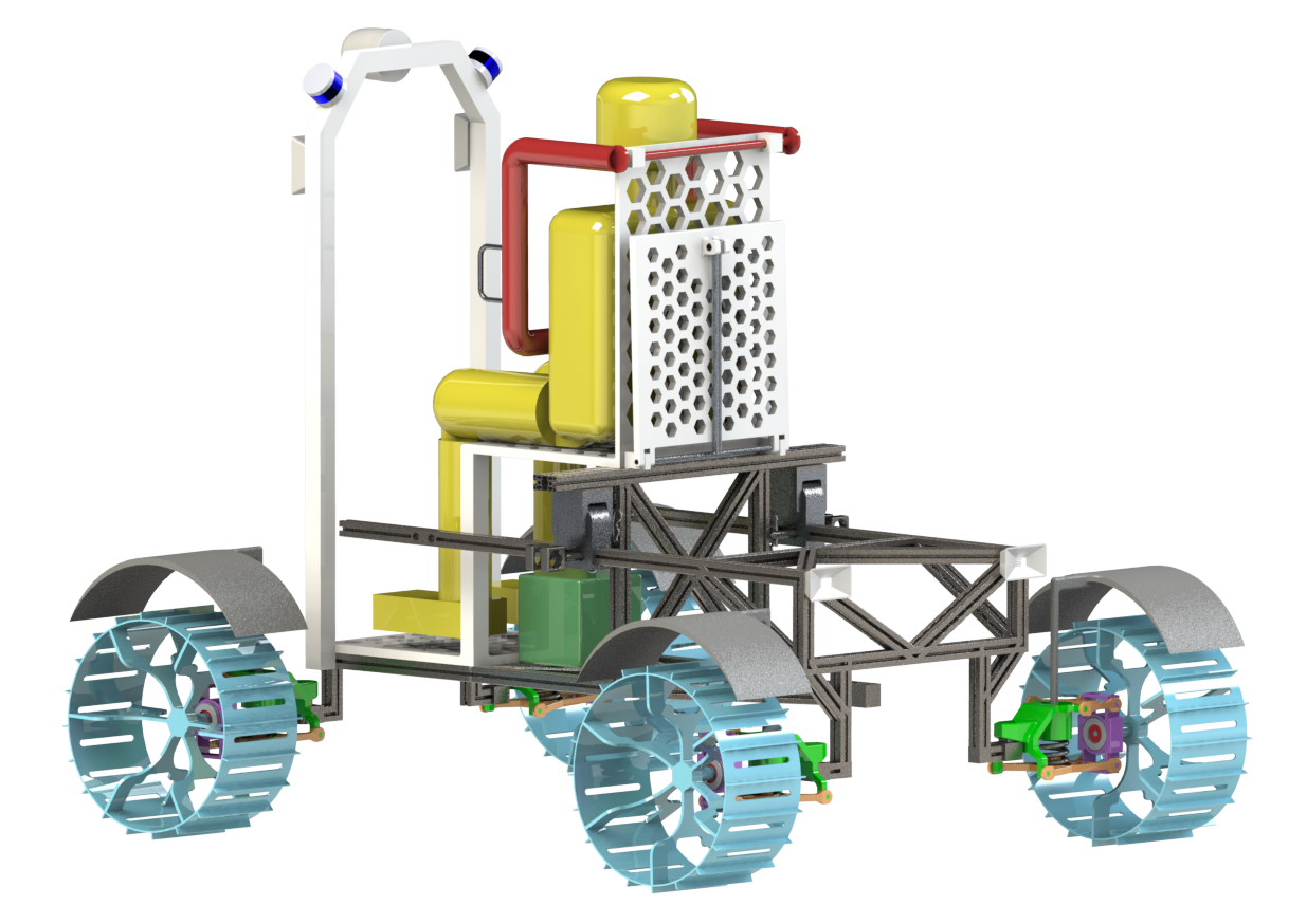
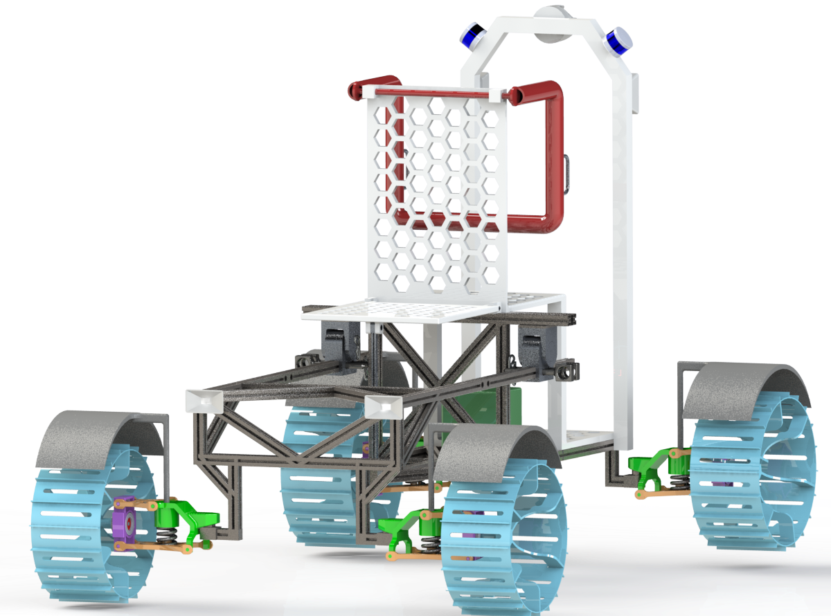
Normal use / Non-Extended Configuration
In the normal use case, the rover accommodates a single astronaut on board. Below you can see different views of the rover empty, with a Lego astronaut, and with Z2 astronauts. Click on any image to enlarge it.
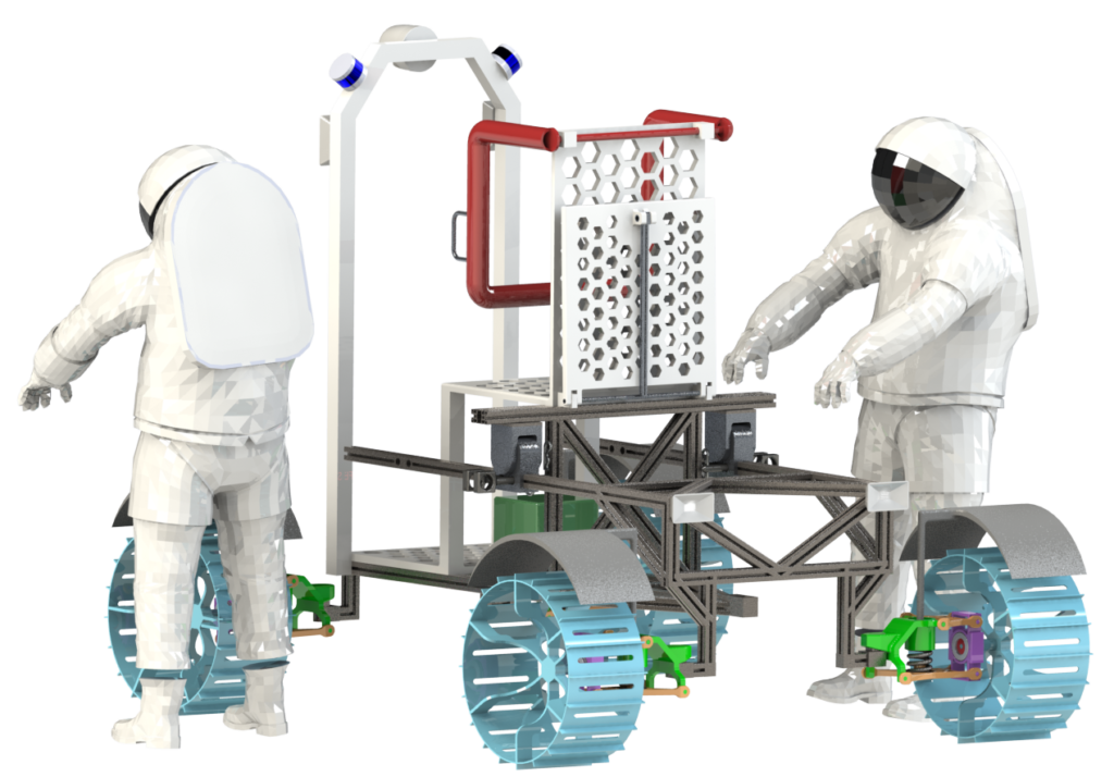
Extension Mechanism and Procedure
The rover is easily reconfigurable between its extended and unextended configurations. First, the astronauts remove the retaining hitch pins on each side of the rover that secure the locking pins in place. Note in the video below there is only one pin on each side – this was later replaced with 2 pins on each side for redundancy and strength. The locking pin can then be removed, and the rover drives its front and rear wheels in opposite directions to pull (or push) the two chassis halves apart (or together). Once the rear chassis has moved to the new position, the locking pins and retaining hitch pins can be easily reinstalled.
Extended Configuration
The extended configuration is designed to accommodate two astronauts in a contingency. For safety reasons, it’s vital that the astronauts have redundancy in the rovers so if one fails while on a sortie, the astronauts on are not stranded.
Ingress/Egress
Ingress and egress into the front (primary) rover seat is very easy. The astronaut steps onto the lower seat platform, climbs in under the sensor arch, turns around and sits down. The seat restraint can then be lowered into place, where it locks to secure the astronaut. Egress works the same way, just in reverse. The red seat restraint is released via a foot pedal (not shown).
Entering and exiting the secondary seat is less straightforward. The high height of the rear chassis assembly makes stepping in difficult (even in casual attire, much less an inflexible EVA suit). We propose a series of fold down steps on the left or right side of the rear chassis (not modeled or shown) to facilitate entry. The 2nd astronaut would deploy the steps, climb up and then in. The 1st astronaut would retract the steps (so they don’t get caught on obstacles or get in the way), and then climb into the front seat.
Sub Assemblies
To get a better understanding of the holistic rover, it’s helpful to explore each of its major subassemblies.
Seat & Restraint
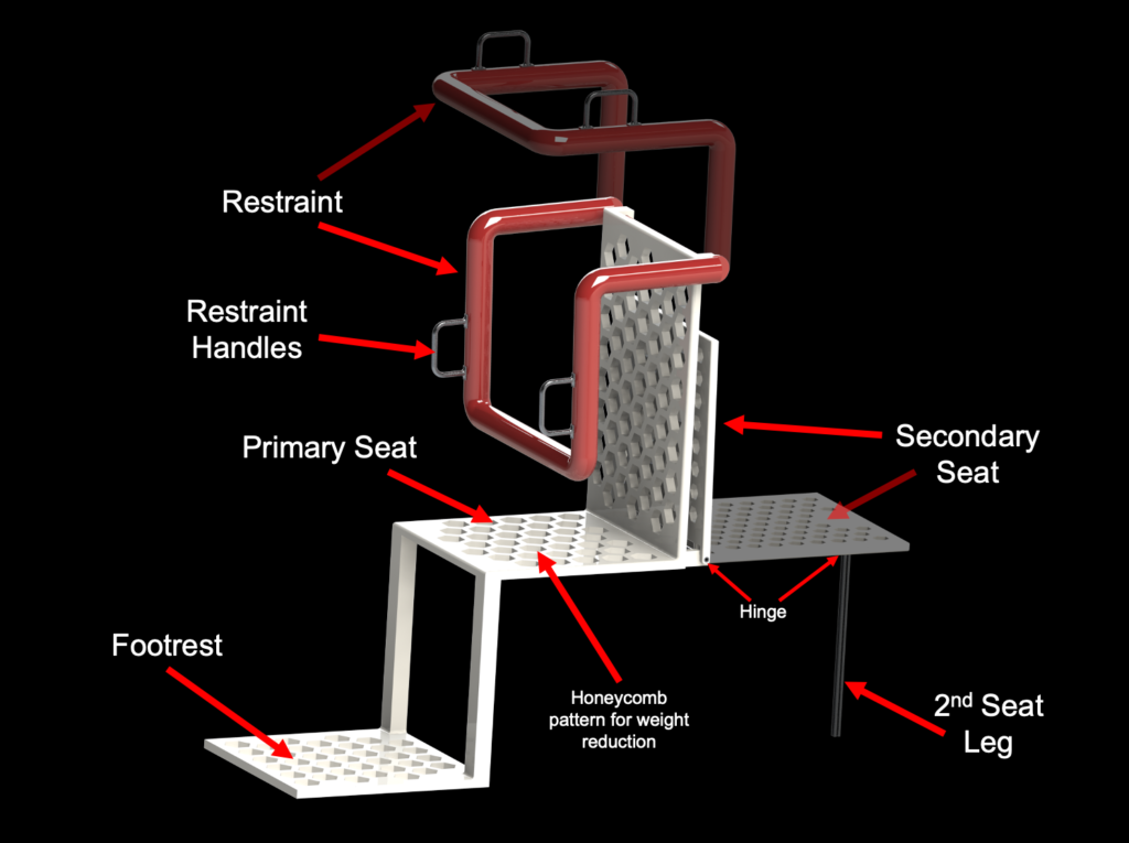
The rover is equipped with two seats to accommodate both EVA astronauts in a contingency. The primary seat faces forward, with the second fold down seat behind it. In the normal configuration, the second seat and leg are folded up and secured via a simple velcro style strap. The primary seat has a rollercoaster style over the should restraint, which lowers to secure the primary astronaut. This restraint locks into place and can be released via a foot pedal (not shown). The restraint includes two handles for the astronaut to hold on to. To reduce weight and complexity, the secondary astronaut is secured with a simple fabric 4 point harness (not shown). Both seats are modeled as a light weight plastic and have a honeycomb pattern for weight reduction. Each astronaut has a 170kg mass, which is a meager 275N weight on the moon. It’s not uncommon for chairs on Earth to be made of thin plastic and a (sometimes) a thin aluminum rim. It’s not hard to imagine that even more lightweight chairs could be used on the lunar surface. You can view an animation of the second seat unfolding and the primary seat restraint closing below.
Leg Structure Check
Let’s model the 2nd seat leg as a pin-pin column. The max weight it must support is the lunar weight of a single astronaut. We actually designed the seat leg to support the Earth weight of an astronaut, giving it a significant safety factory for use on the moon.
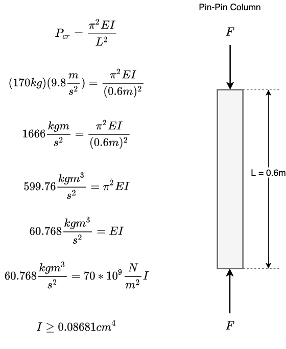
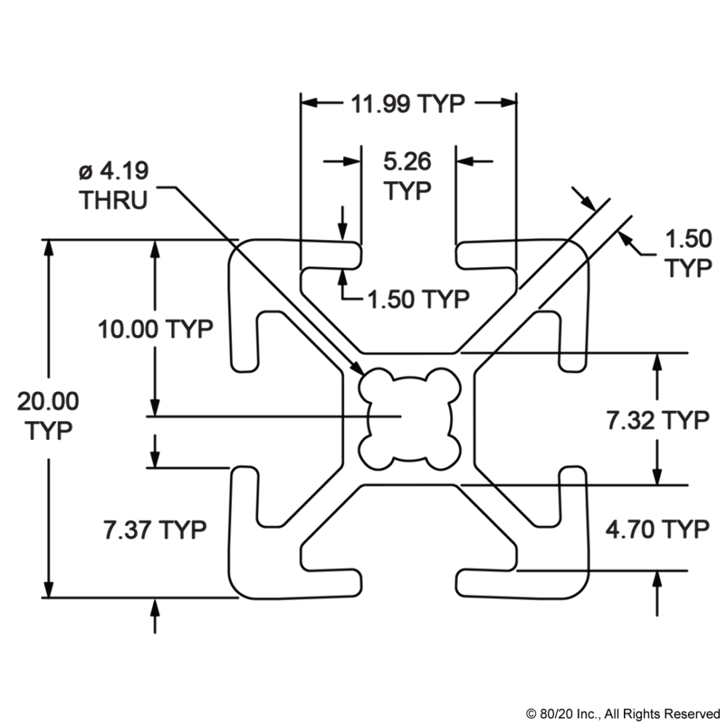
From our brief analysis, we need a beam with a moment of inertia greater than or equal to 0.08681cm^4. For modeling simplicity, we used an 8020 20-2020 aluminum beam, which has a moment of inertia of 0.6826cm^4, far exceeding the requirements of this component. More rigorous and lunar focused analysis would certainly produce a more weight efficient design for this component.
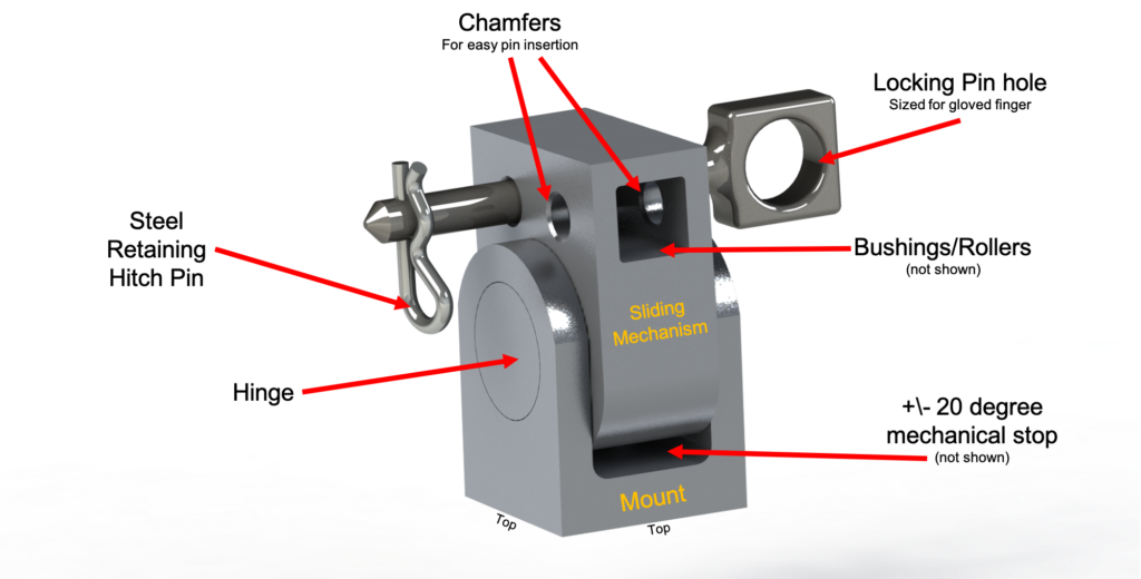
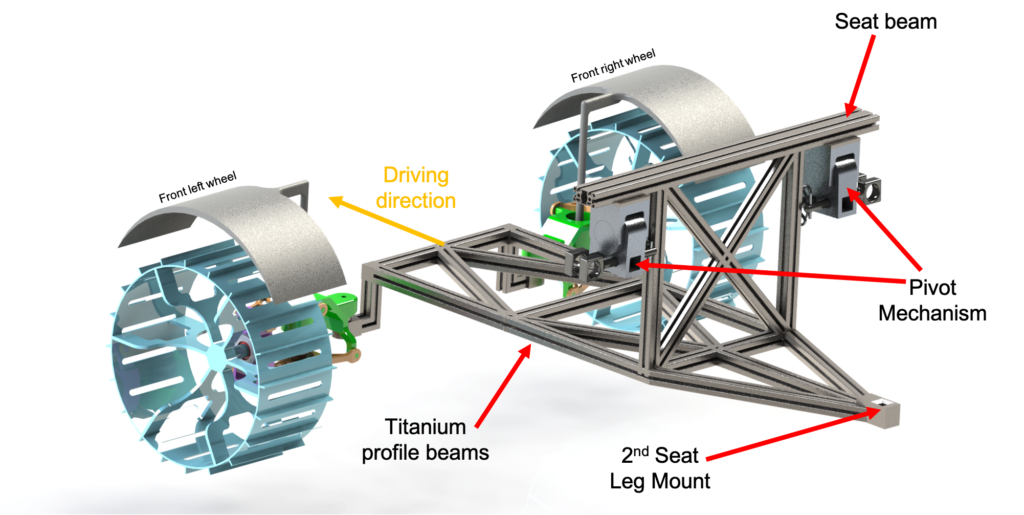
Pivot Mechanism
The pivot mechanism allows the two chassis halves to not be coplanar. Two pivot mechanisms interface between the front and rear chassis, one on the left and one on the right side. The pivot mechanism is comprised of several components – a mount (which sits on the underside of the front chassis seat beam), the pivot hinge (which connects the mount and the sliding mechanism), and the sliding mechanism. The sliding mechanism is an aluminum block with a hollow section the same geometry as the rear chassis extender beams. Inside this space are either bushings or rollers (like a skatewheel conveyor) that allow the rear chassis extender beams to slide easily. The extender beams are secured in place via two steel locking pins. Each of the locking pins are kept in place via a steel retaining hitch pin.
Front Chassis
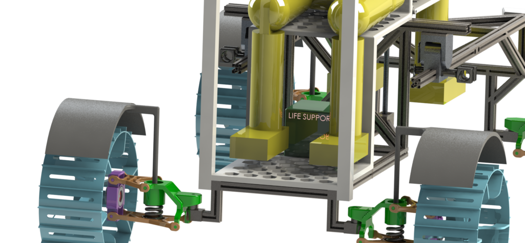
The front chassis assembly integrates the front two wheels and both pivot mechanisms with an 8020 4545-Lite titanium profile frame. The full seat assembly sits on top of the front chassis and seat beam. The rear end of the front chassis has a mount for the leg of the 2nd seat. The life support payload (shown as a green box in some above renders) sits below the seat on the front chassis frame.
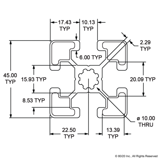
Both the front and rear chassis are modeled primarily out of 8020 45-4545-Lite titanium extrusion beams. We assumed that any 8020 profile would have a better strength to weight ratio than we could design on short order, and serve as a decent placeholder for the final vehicular structure and mass. It’s likely that the chassis designs you see here are over-designed and could be made more lightweight. This class was not a structures or materials course, and rigorous analysis of the strength and rigidity of the rover was largely considered out of scope. The pattern of bracing stems primarily from our own engineering intuition on what might be required for a sufficiently sturdy and stiff frame. An earlier chassis design used 8020’s 45-9090 Aluminum profile, but our analysis at the time (which you can read about towards the end of this document) suggested that we could reduce weight with acceptable losses in rigidity by switching to a titanium 4545-Lite profile.
Rear Chassis
The rear chassis integrates the rear two wheels and the extension beams with an 8020 4545-Lite titanium profile frame.
Sensor Arch
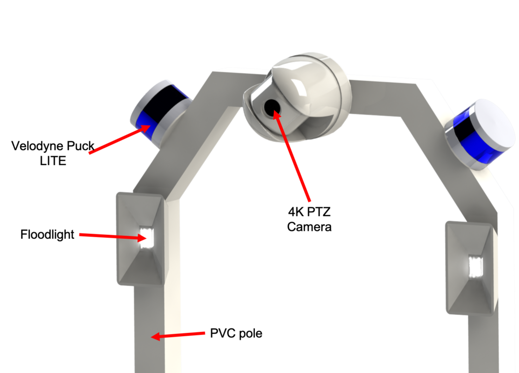
The sensor arch elevates several floodlights, LiDAR, and cameras, providing them with a better vantage. These components weigh very little, so the sensor arch does not require much structural strength. Its modeled as a hollow square PVC pipe. Again, the extreme temperature ranges on the moon make plastic impractical, and a more moon compatible material would need to be used. For the purposes of this project, the PVC Earth analog is sufficient.
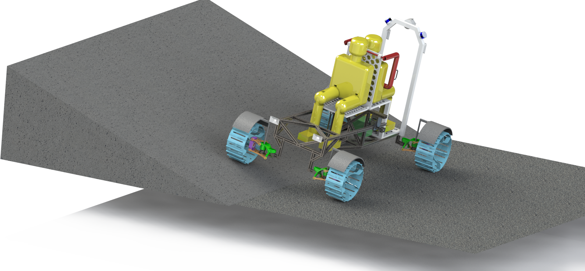
Trafficability
We needed to analyze how the rover handles a variety of obstacles – a 20 degree slope (in any direction), a 0.1m obstacle under any wheel, and/or a 0.3m obstacle under any wheel. Our analysis revealed only small perturbations in the location of the center of mass of the rover (fully loaded) on any obstacle combination, which make the system statically stable for all required conditions (if the center of mass, projected on the ground plane, ever exceeded the bounds of the convex polygon of the wheels, the rover would tip). For rigorous analysis of the changing center of mass with various obstacles, please see the “Independent Suspension Calculations” section above and “suspension.mlx” on the Github. Here you can see some renders of approximate chassis poses with different obstacles. These renders don’t fully account for the flexibility of the suspension system or the natural weight distribution that would occur on the moon (due to inflexibilities in the model).
First, let’s look at the rover with a single 0.1m obstacle.
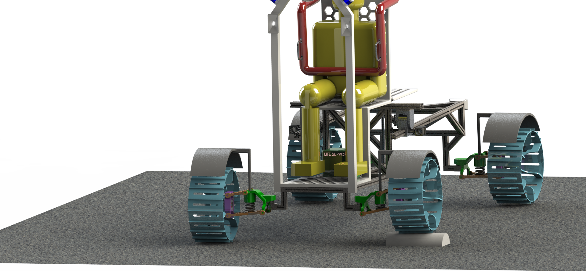
The rover handles that pretty easily. Let’s now look at a 0.3m obstacle. Due to model constraints, the rover is much more tilted than it would be in real life, but still the rover is able to overcome this obstacle.
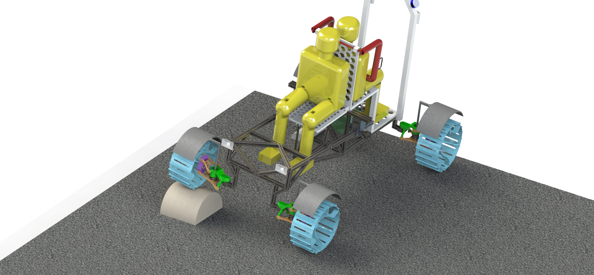
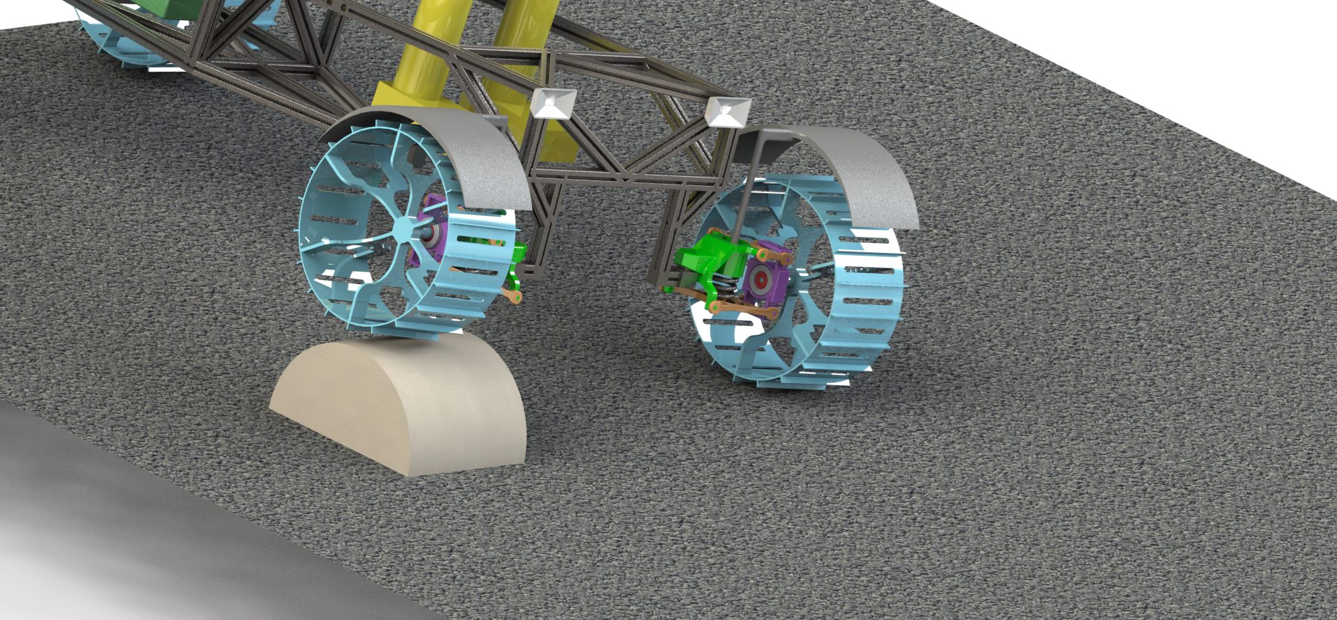
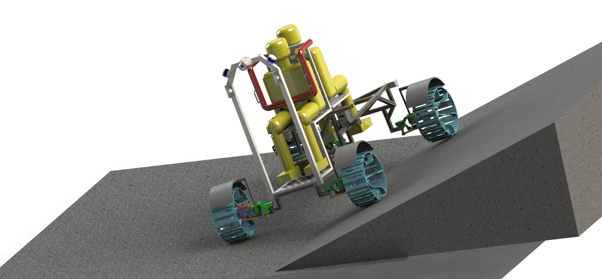
You’ve already seen the pivot mechanism, but perhaps the utility of such a feature is not yet clear. See how the rover handles exiting a slope, with it’s rear wheels up a 20 degree hill and it’s front wheels on flat ground.
It shouldn’t surprise you to know that the pivot mechanism works the same way with the rover going up hill – front wheels on the 20 degree slope, rear wheels on flat ground.
The pivot mechanism doesn’t help at all if the rover is sideways on a hill, but that case is handled by the suspension. This render doesn’t accurately account for the flexibility of the suspension system – the suspension should absorb more of the difference and leave the chassis closer to level.
Logo and Name
The rover mission name, “Courage”, comes from a NASA list of finalists for the Mars 2020 (now “Perseverance”) Rover. We liked the tradition of naming missions after human qualities, and wanted to continue that with this project. The slogan “Ad fortiter ire | Ad infinitm, et ultra” is Latin for “To Bravely Go | To Infinity and Beyond”. The first part of this is partially inspired by Star Trek (“Space: the final frontier. These are the voyages of the starship Enterprise. Its continuing mission: to explore strange new worlds…To boldly go where no one has gone before!“) and modified to match the Courageous theme of the mission title. The second half is inspired by Toy Story’s Buzz Lightyear who often says the same phrase.
Earth and Mars Efficacy
Part of this project was to evaluate our lunar rover design for use on both Earth and Mars. The primary differences between these three planetoids (for the purposes of this project) are soil properties and gravity.
The rover design can be said valid for any environment if the rover satisfies the following conditions.
- The rover wheels have sufficient traction power to get the rover moving. This can be easily determined from the drawbar pull force using the soil characteristic properties.
- The configurations of rover is stable in that particular environment. The stability calculations can determine the validity of static and dynamic stability of the rover.
Using soil characteristics for Earth and Mars [1] and assuming shear deformation modulus to be same as Moon, the drawbar pull of the wheels on both Earth and Mars was calculated. The drawbar pull of the rover on Earth was 6154.99 N and on Mars was 968.26 N for sandy loam soil and 7713.51 N for slope soil. From the figure below In Figure 16a, the stability calculations of the rover in non-extended and extended configuration on Earth shows that the rover is static stable as well as can travel uphill at an angle over 30° and downhill at an angle less than 10°. On Mars, the rover can travel uphill at an angle over 30° and downhill at an angle greater than 10°.
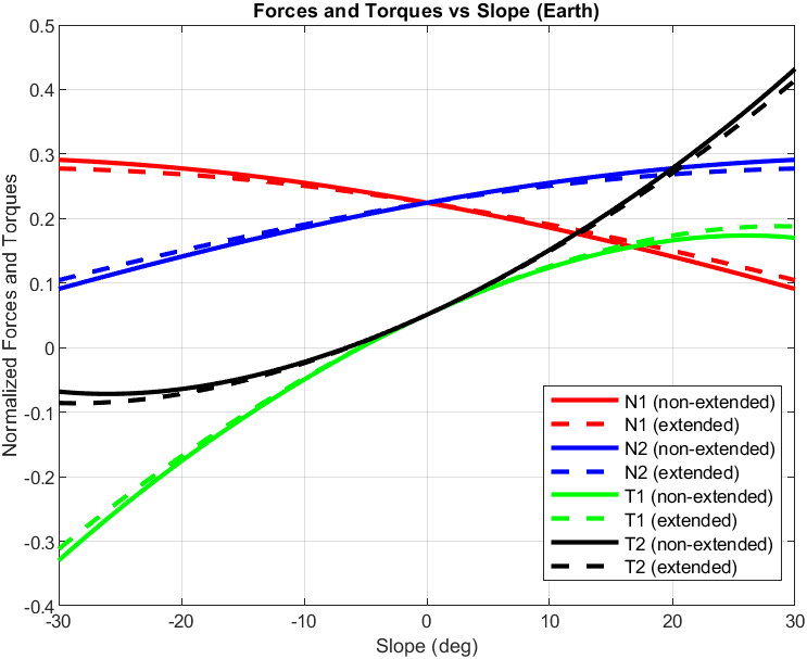
Stability on Earth 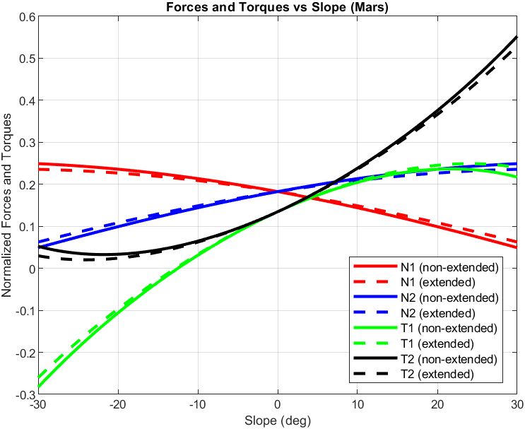
Stability on Mars
The values from the drawbar pull calculation and the stability calculations lead to the conclusion that both non-extended and extended configuration of the rover design is valid for Earth and Mars environment.
Design Evolution
“3) Design is an iterative process. The necessary number of iterations is one more than the number you have currently done. This is true at any point in time. 4) Your best design efforts will inevitably wind up being useless in the final design”
— Akin’s Laws of Spacecraft Design
Inspirational Designs
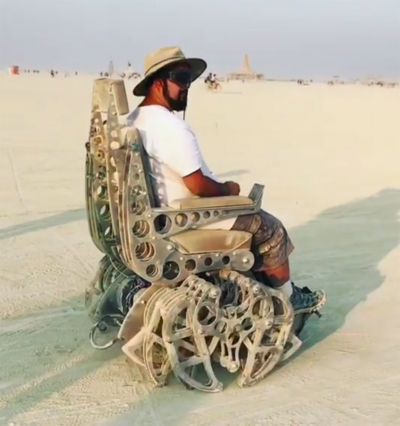
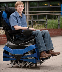
We explored a number of inspirational concepts early in the design phase. Briefly, these included vehicles with very large wheels (a Lunar “Monster Truck”), high speed vehicles with treads, systems with high DoF suspension/leg articulation, and vehicles with tread assemblies instead of wheels. While our final design borrows little from these concepts, we still believe many of them still have merit and are worth further investigation.
Concept Sketches and Early Designs
Safety
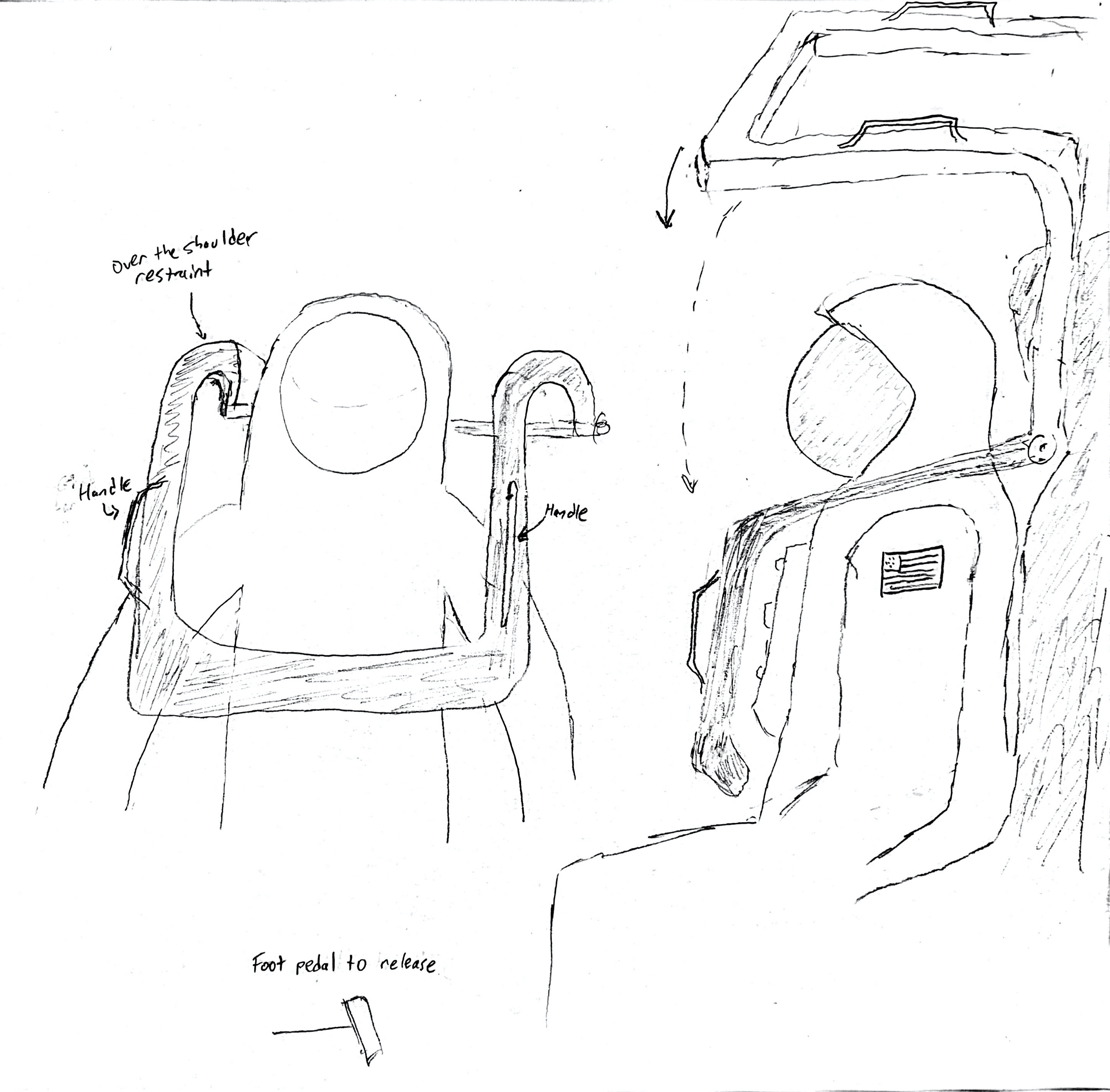
Early in the project we knew we wanted to incorporate safety restraints. EVA suit gloves are stiff and not very dexterous, which would make a traditional car 3 point harness difficult to use. Instead, the astronaut is secured in their seat with a rollercoaster style over the shoulder restraint. This restraint includes handlebars and can be released via a foot pedal.
Umbilical Management
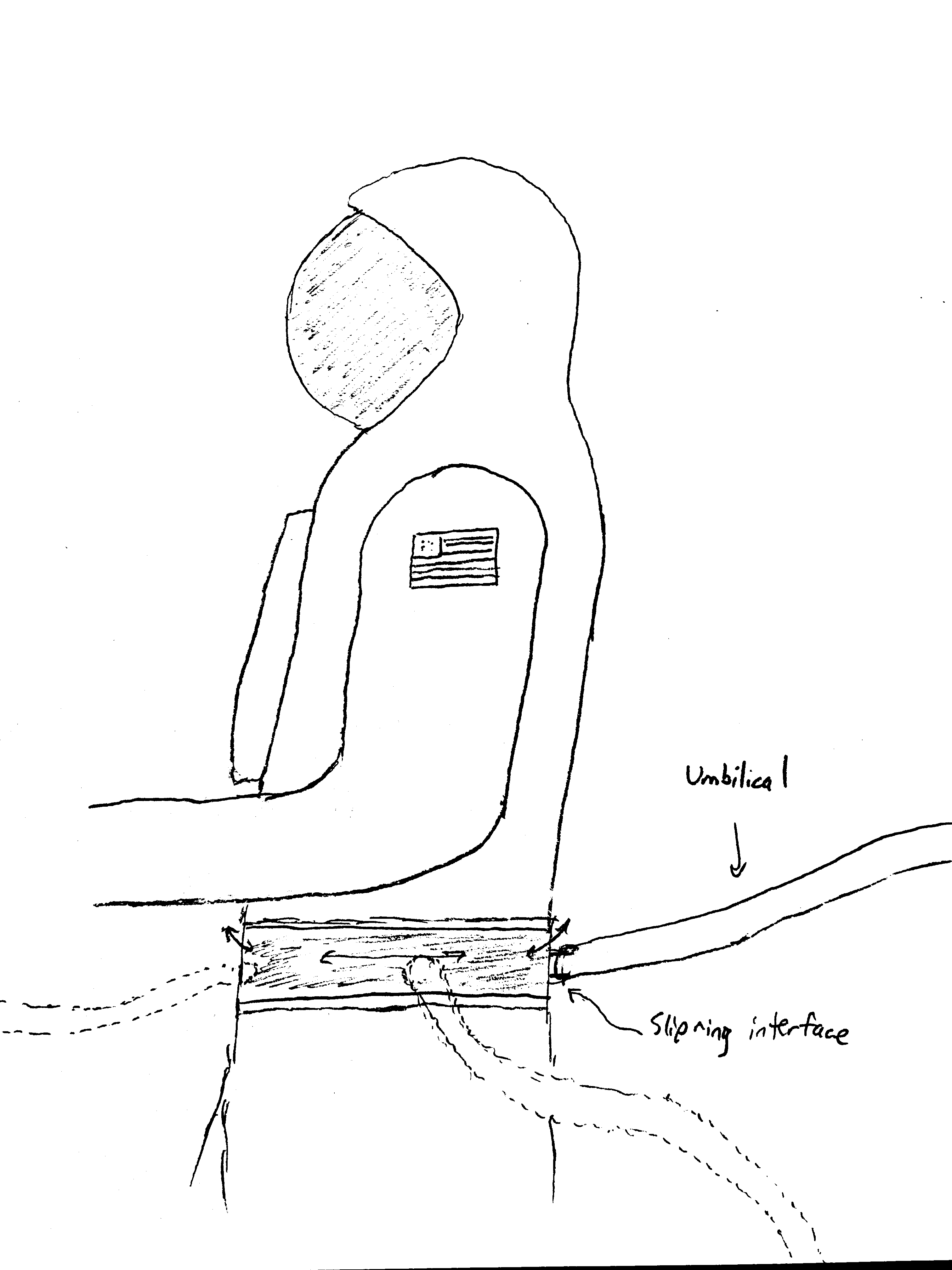
Astronaut mobility and flexibility is key to this mission. We don’t want the astronaut getting tangled in their life support umbilical hosing or be restricted in movement by its presence. The astronaut’s umbilical hose connects to their EVA suit via a slip ring interface at their waist, which allows the hose to rotate freely around the astronaut as they move. This particular suit element would likely require significant research and development (far exceeding the scope of this project) to be practical and safe.
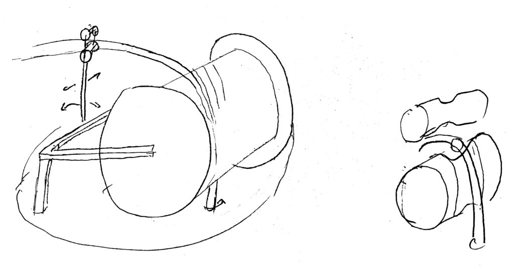
We also drew preliminary designs for an umbilical management system. The umbilical hose is wound on a large spool, which is then mounted on freely rotating platform. The turntable base allows the umbilical to always face the astronaut (for minimum hose tension). The spool allows additional hose length to be drawn as necessary, and includes a motor to rewind the hose. The umbilical hose is fed through double rollers on an arm for reduced friction. The turntable base connects to the umbilical hose via a slip ring interface, and internal hoses in the chassis connect this junction to the life support payload.
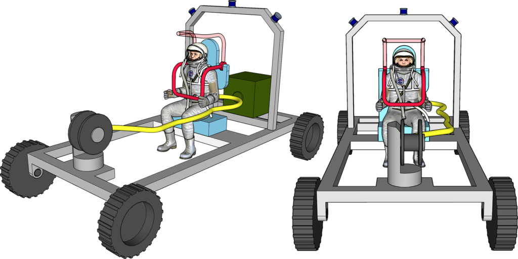
Mk1 Rover
The Mk1 rover was a preliminary layout prototype. It draws heavily from the Apollo LRV, and features 4 wheels with individual suspension. This design incorporates a sensor arch, on which Li-DAR, lights, and cameras are mounted, as well as our roller coaster style seat restraint, both of which were incorporated in our final design. This system also demonstrates an umbilical management system (at the front of the vehicle) which is mounted on a rotating platform to always face the astronaut. There are many similarities between this design and our final design in terms of general structure and layout. However, this design was poorly sized (both too long and too wide) and doesn’t easily accommodate a second astronaut. In this configuration, one option for a second astronaut was to have the seat (on both rovers) be mounted on a track. In the contingency case, the seat on the first rover would slide sideways, and the seat from the second rover could be detached and added to the first. However, in an emergency situation, this amount of rover reconfiguration is highly impractical, especially if the seats are heavy.
Horsebot
After the midterm presentation, we pivoted away from a traditional car inspired rover and began looking at more novel, bio-inspired concepts. The Horsebot was our next major design concept. It’s (as the name implies) a horse inspired design with four 4 DoF legs (there is an additional hip rotation joint that is not shown in Figure below). The green box is our 80kg life support payload (0.25m on a side). There is a fold down seat in the rear of the vehicle to accommodate the second astronaut in the contingency situation.
Pros
There were a number of benefits to this idea that made it appealing. The tall legged locomotion easily clears any obstacle, and works well on rugged/uneven terrain. The hip joint has an additional 360° hip rotation joint (not shown) which allows Horsebot to walk sideways (or at any arbitrary angle) with its standard (“forward”) gait. The incorporation of a second, fold down seat makes it easy to incorporate a second astronaut (this fold down seat is one element of this design that was kept for the final design). The integrated primary seat is strategically positioned to maintain a relatively low center of mass, which is great for stability. (A more directly horse inspired design would have the rider atop the vehicle; much higher up). Ingress and egress in this design are very easy. The right side of the vehicle is open to allow the astronaut to enter with ease, and the entire system can “kneel” (lower itself closer to the ground) to allow the astronaut to simply step onto the foot rest (level with or close to the ground)
Cons
While there are several legged locomotion robots (ex: Cheetah, Spot, ANYmal) in various stages of development, we do not yet have a robotic horse analog on Earth. Robotic legged locomotion with a human passenger is not a well tested concept, and should be proven feasible on Earth first before it is attempted on the Moon.
By their nature, legs are more complex than wheels (ignoring suspension) and therefore offer more avenues for failure. Unlike a wheeled vehicle, which requires 2 motors per wheel (driving and steering), this Horsebot design requires 4+ actuators per leg (for 16+ actuators), which significantly increases the total weight of the system and it’s required power. Additional Degrees of Freedom, such as one for hip abduction and another for ankle pronation, might be required for walking on slopes.
The project details require that the rover be capable of a max speed of 4m/s. This speed would require a medium trot or a slow gallop gait, which are only dynamically stable. Trot/Gallop gaits require much faster and higher torque motors, which then drive up the weight and power. An Earth gallop gait is likely not directly reproducible in the 1/6th gravity of the moon.
Wheeled Horse
The wheeled horse concept is similar to the Horsebot shown above, but includes wheels (mounted on either the ankles or knees) for a reconfigurable driving configuration. Obstacle avoidance would be done at slow speeds with a walking gait, while normal (higher speed) travel on smooth ground would be done with the wheels. This reduces the need for high speed/torque motors for a gallop/trot gait, but requires an additional motor for each wheel. The leg motors act as electromechanical suspension in driving mode. The added complexity and weight of the wheels and their driving motors makes this idea less practical than either a traditional wheeled rover or the original Horsebot.
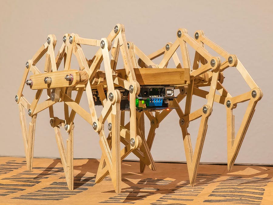
Strandbeest
While exploring options for legged locomotion, we briefly evaluated a series of designs inspired by Theo Jansen’s Strandbeests and other similar designs. These designs allow for complex leg articulation with very few motors, and can be made to be fairly lightweight. However, the legs have very high mechanical complexity, which offers many different failure modes. Many of these designs are well tested on sand, but few (if any) are well tested on rugged/uneven terrain, and they are largely incompatible with stair climbing due to their leg lengths.
6 Wheels with Extendable Chassis
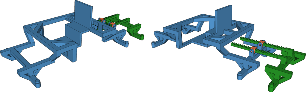
This concept involves a 6 wheel rover with two possible configurations. In the normal driving mode, the rear 4 wheels are close together and act as tandem wheels. In the contingency configuration, the chassis extends to provide a longer base so the shifted center of mass (due to the second astronaut) is still centered (front/back) on the rover. In its original implementation, this extension would be actuated via a hand crank which turned a pinion to move the rack (the extender). Subsequent iterations on this design used two extending beams (as shown in the figure below) for improved stability, as well as an additional pivot (orange, in the figure below), allowing for the rear wheels to not be coplanar with the rest of the rover (ex: exiting a hill). A later design iteration abandons the crank and rack/pinion and uses the wheels driving in opposite directions to separate the two chassis halves.
6 Wheels with Chassis Arch
This was one of more recent design iterations, and among the first to be realized in SolidWorks. Much of this assembly (nearly everything except the chassis) was reused in all subsequent designs. This was the first design to incorporate an 8020 extrusion profile for the chassis structure. We figured that the 8020 beam profiles would have a far high strength to weight ratio than we could design in such short time. Originally modeled with an aluminum 45-9090 beam, the chassis was later switched to a titanium 45-4545 Lite beam profile for greatly improved weight reduction at the cost of a small bit of structural rigidity.
Structural Analysis
We briefly evaluated the structural requirements of the top of the rear chassis arch. We approximate this as a beam like shown below.
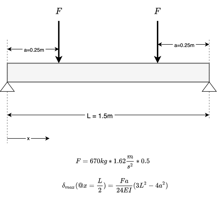
The deflection equation finds us the maximum deflection at the center of the beam. An 8020 45-9090 Type Aluminum Extrusion has the following properties:
$$\text{Young’s Modulus} =E = 70×10^9 Pa$$
$$I = 179.4968 cm^4$$
$$A = 20.014cm^2$$
Total Mass: 8.104kg
Maximum deflection = 0.29mm
An 8020 45-4545-Lite Titanium extrusion has the following properties:
$$\text{Young’s Modulus} =E =170×10^9 Pa$$
$$I = 9.2029 cm^4$$
$$A = 5.167 cm^2$$
Total Mass: 3.49kg
Maximum deflection = 3.3mm
This constitutes a significant weight reduction with only a small gain in deflection. 3.3mm is approximately the thickness of two US Quarters, which seems acceptable.
4 Wheels with Chassis Arch
The middle two wheels in the 6 wheel design were excluded from our stability calculations (as well as other evaluations) and we realized that these two wheels contributed little except additional driving power and structural stability. Evaluating a 4 wheel rover proved much simpler than trying to evaluate a 6 wheel rover, and the middle two wheels (and entire middle chassis assembly) were discarded.
4 Wheels with Flat Chassis
The chassis arches were designed to get the rover body higher off the ground so that it wouldn’t catch on obstacles. However, our wheel design places the wheel hub 0.3m above the ground, so any chassis flush with or slightly above the wheel axles would satisfy this obstacle avoidance requirement. This next iteration of the design focuses on a much flatter chassis for simplicity and strength. This would become our final design, with additional braces and structural reinforcement for improved rigidity and strength.
Calculations and CAD Models
The entire works related to this project are accessible via our Github page: https://github.com/BrianBock/ENAE788x_Project. You can view our final presentation and many more associated videos/animations/renders at https://drive.google.com/drive/folders/113_ eTfvzxWGKhZmb-tjgHEhFOzATDLpB?usp=sharing. The slides include many additional views of many components of the finalized rover as well as each of the concept designs.
Future Work
With additional time and resources, there are a number of additional design improvements that we’d like to explore.
Suspension: While we believe our suspension system (as designed) satisfies the project requirements, having a larger, more robust suspension would empower the rover to handle larger obstacles and more uneven terrain.
Extender Beam Safety: The pivot aspect of the rear chassis extender mechanism poses a nontrivial safety risk. The potentially rapidly moving rear extender beams could pinch/crush or otherwise injure an astronaut’s fingers/toes or other extremities. To mitigate this issue, we propose a safety covering or sheath around the extender beams. This covering would extend from the floor to the maximum height of the beam, and could be made of plastic or metal, and be either solid or cage-like.
Ingress: While it is easy to step into the front (primary) seat, the higher geometry of the rear chassis makes entering the 2nd seat much more difficult, especially in a stiff legged EVA suit. The easiest way to enter that seat would be via a fold out set of stairs on the rover side (either left or right) that would give the 2nd astronaut smaller steps to climb up.
Structure: We expect that a more rigorous structural analysis of the chassis design would result in improved strength and decreased weight of the structure. It’s likely that an exploration of advanced manufacturing techniques (ex: Direct Metal Laser Sintering) combined with computational design methods (FEA, Topology Optimization) could produce chassis geometries with an even greater strength to weight ratio.
Storage: A future version of this chassis design should incorporate cargo/stowage space for samples and tools.
Image and Model Credits
Moon image used in logo from https://en.wikipedia.org/wiki/Moon
Z2 Astronaut from https://nasa3d.arc.nasa.gov/detail/nmss-z
Mercury Astronaut from https://3dwarehouse.sketchup.com/model/a12f9d60010ffc9c1d87a20dd756a828/3D-MERCURY-ASTRONAUT
8020 Beam Profiles from 8020.net and https://www.3dcontentcentral.co
Velodyne Puck LITE from https://velodynelidar.com/products/puck-lite/
References and Additional Reading
[1] D. Akin, “Lecture 6: Terramechanics,” September 2020. [Online]. Available: https://spacecraft.ssl.umd.edu/academics/788XF20/ 788XF20L06.terramechanics1x.pdf
[2] ——, “Lecture 7: Terramechanics,” September 2020. [Online]. Available: https://spacecraft.ssl.umd.edu/academics/788XF20/ 788XF20L07.terramechanics2x.pdf
[3] ——, “Lecture 11: Akin’s Pocket Guide to Terramechanics Analysis,” October 2020. [Online]. Available: https: //spacecraft.ssl.umd.edu/academics/788XF20/788XF20L11.stabilityx.pdf
[4] ——, “Lecture 26: Independent Suspension Calculations and Wheel Steering Torque Estimation,” December 2020. [Online]. Available: https://spacecraft.ssl.umd.edu/academics/788XF20/788XF20L26.kinematics2.pdf
[5] Velodyne, “Velodyne Lidar Puck LITE; Light Weight Real-Time Lidar Sensor,” 2019. [Online]. Available: https: //velodynelidar.com/products/puck-lite/
All of Dr. Akin’s lectures were utilized in the development of this project.