I’m really excited about the progress I made this week.
The cameras I’m using have two screws in the back that hold the lens in place. These screw protrude about 1.2mm, making the back face of the camera uneven. I knew that I would need to do something to make the camera flush, otherwise it would rock when screwed in, and could crack if over tightened. To resolve this, I quickly modeled a wafer plate to back each camera, and printed one.
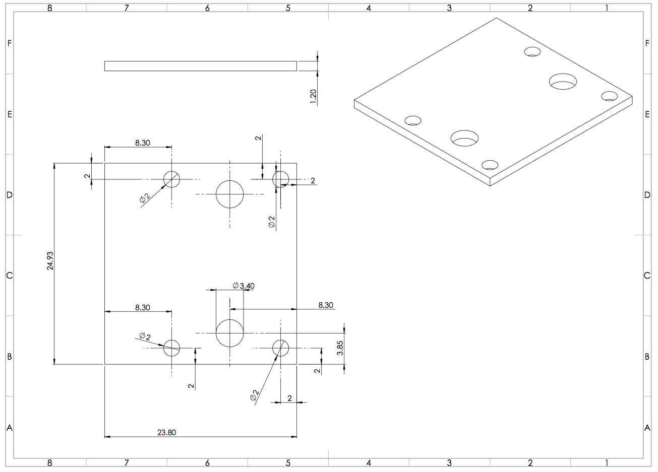
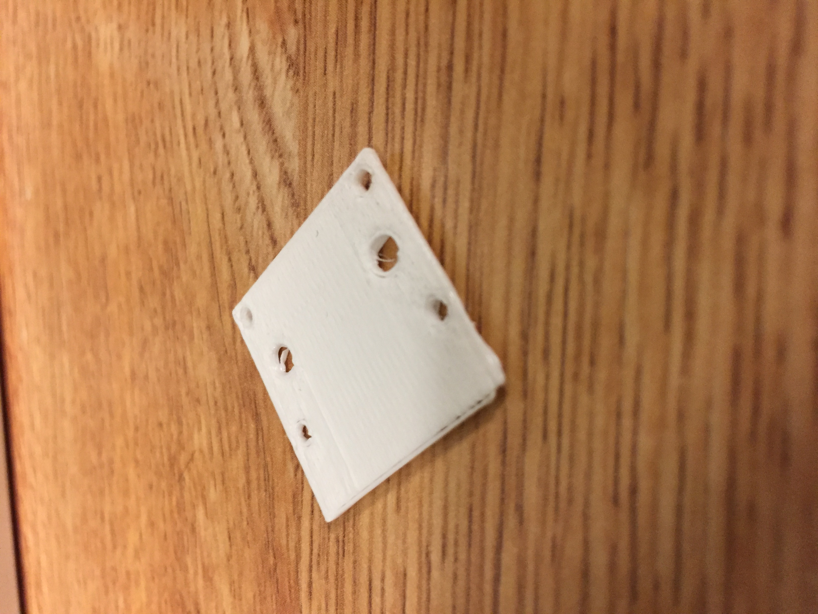
It printed sloppily and didn’t fit nicely on the camera, so I went back and made a few modifications.
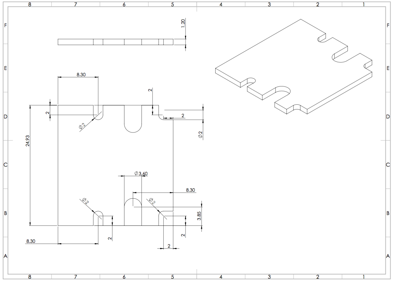
This revision included larger holes for all screws and U shaped notches instead of circles. I printed this in black and it fit the camera perfectly! Satisfied with the alignment and fit, I reprinted this 8 minute print another 3 times, one for each of the remaining cameras.
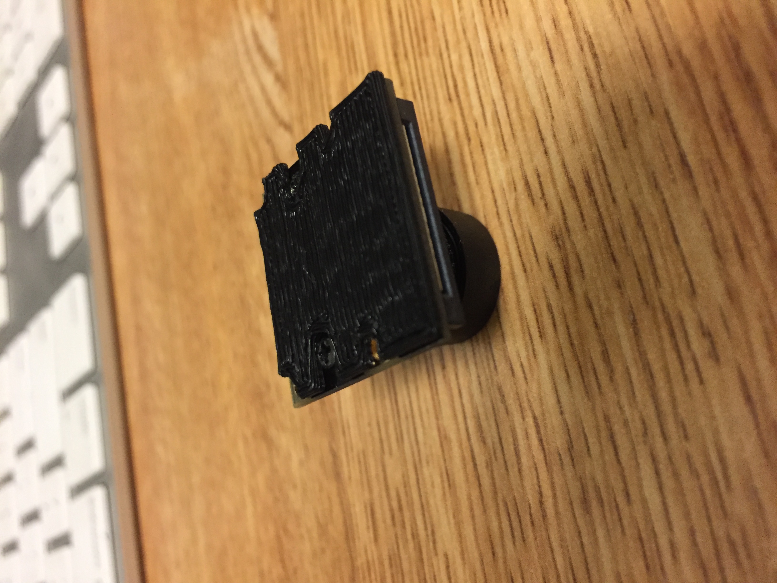
I affixed these plates to the cameras with some double sided tape. The cameras now had a smooth flat back and were ready to be mounted.
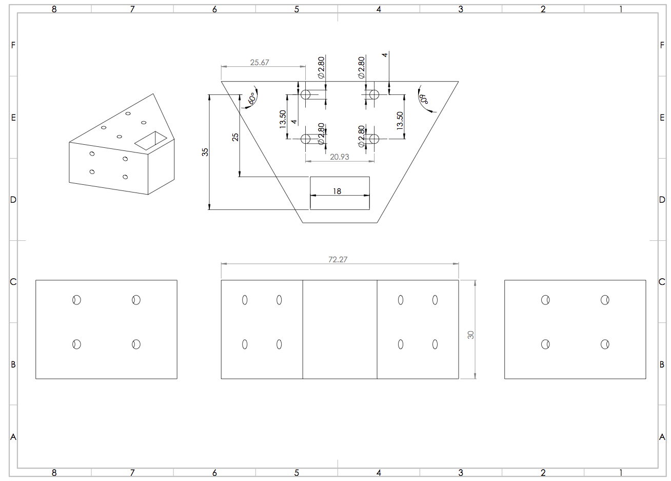
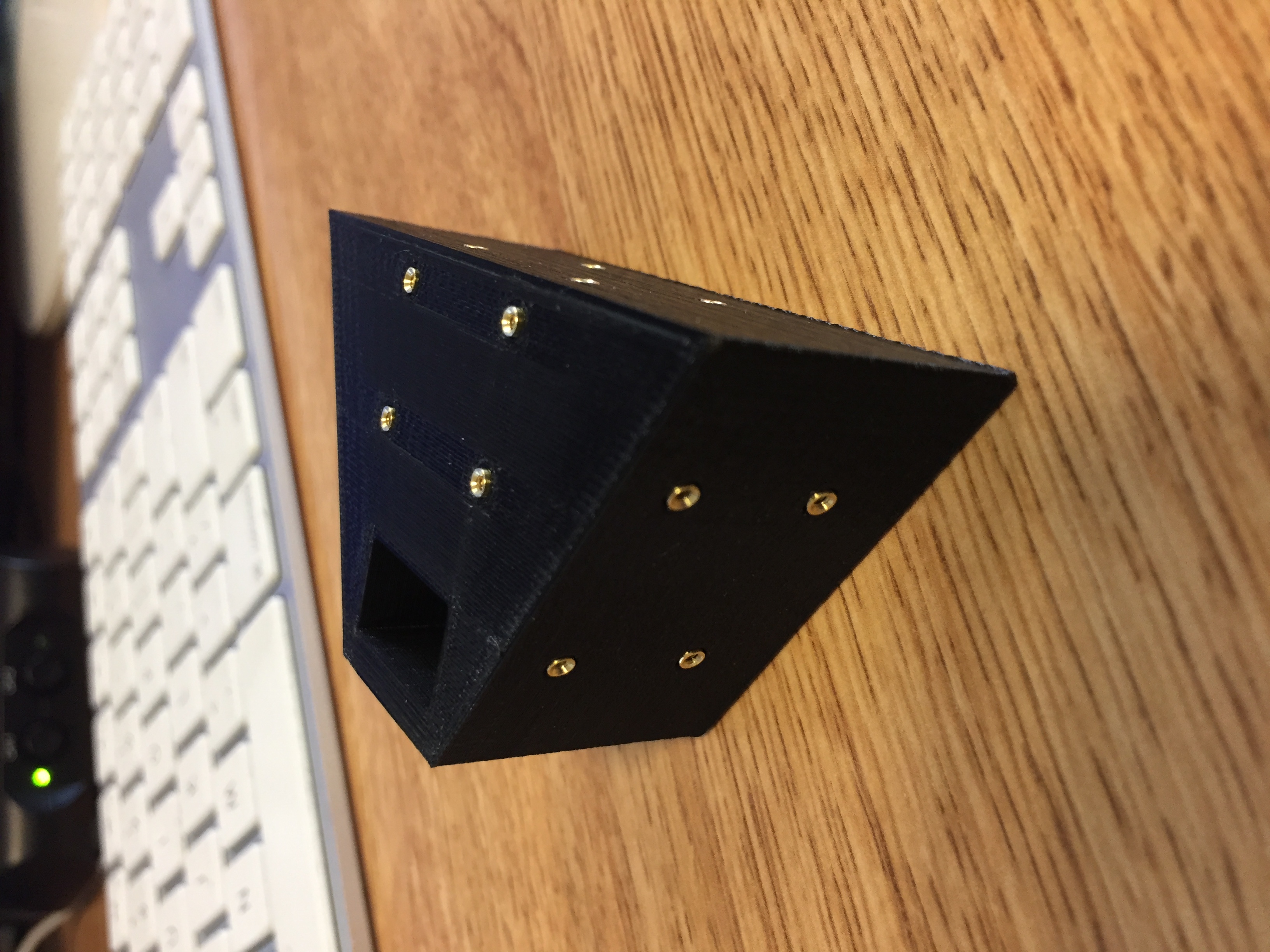
I modified my original triangle camera mount to include four screw holes for each camera. McMaster Carr, the manufacturer of the brass screw inserts, recommended a hole diameter of 3/32”=2.38mm. I made these holes with a 1.3mm radius (2.6mm diameter) to allow for some tolerance on the 3D printer. The part printed in about 2 hours without issue. I had great difficulty getting the screw inserts into these holes, and ended up hammering the first three to get them into place. This process, in addition to being disruptive to my neighbors, was tedious and unproductive.
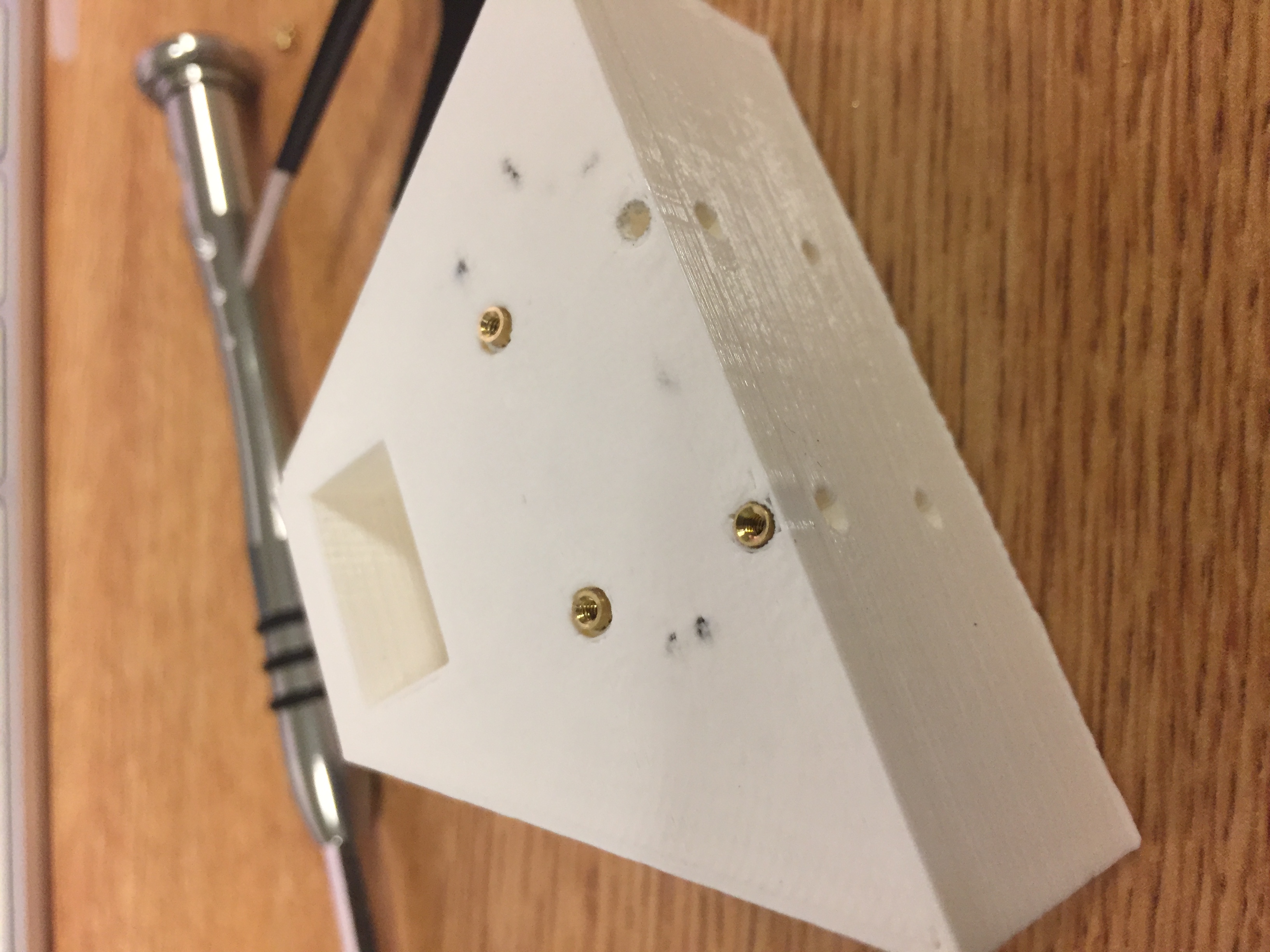
I went back to the Solidworks file, modified each hole to have a 1.4mm radius (2.8mm diameter), and reprinted it in black.
Using tweezers, I was much more easily able to fit the screw inserts into the larger holes.
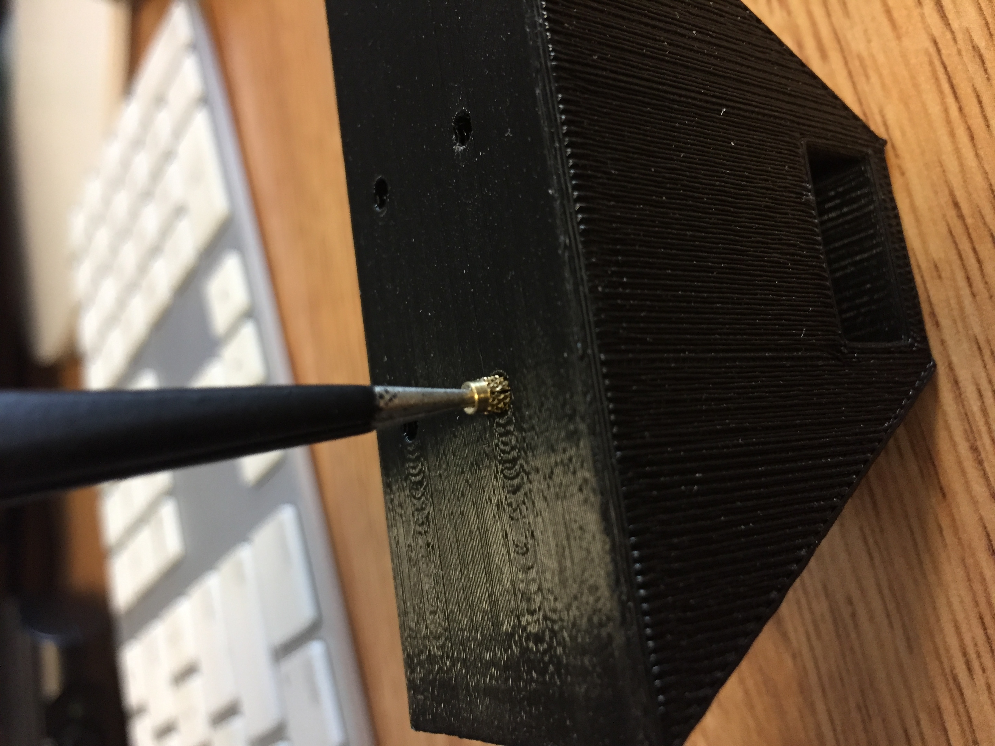
They slid in snugly and expand with the screws inside them, providing a secure mount.
 A few minutes later, I had all the screw inserts in place. I began attaching the cameras.
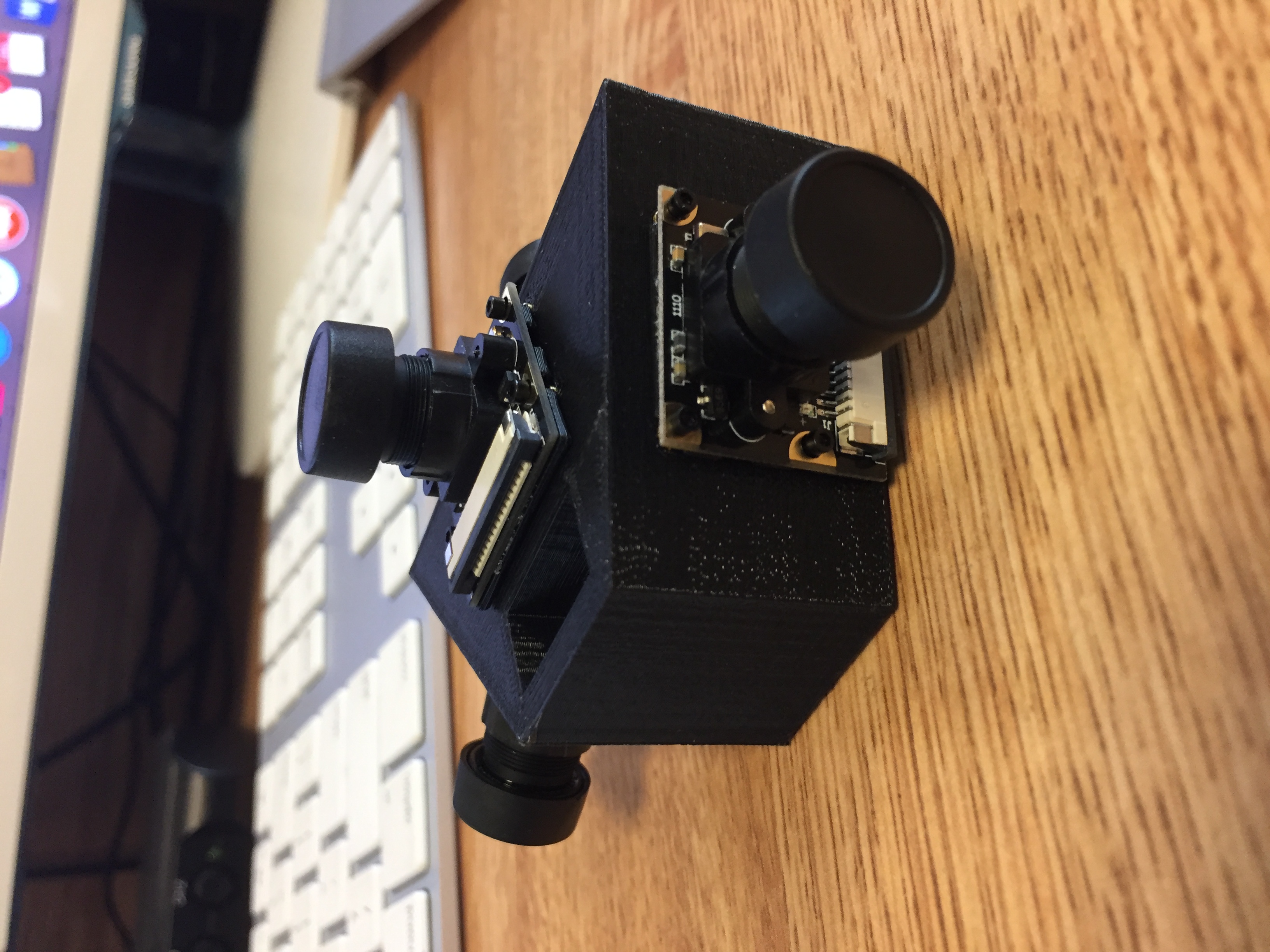
I was thrilled to see my design become a physical reality, and really pleased with how closely this ‘final’ product matched my drawing. This coming week, I need to connect all of these cameras to their respective Pi Zeros and verify that this configuration covers what I need it to. I had previously built modeled projections of each camera’s view based on viewing angle listed by the manufacturer. I think these projections are valid, but I made some assumptions while making them.
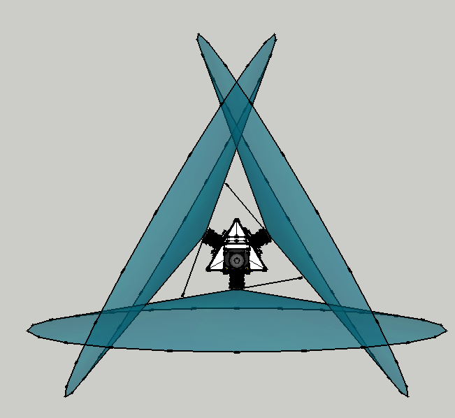
The field of view of each camera is visualized with a semitransparent cone with a 160 degree vertex. Theoretically, this camera configuration should work, but I won’t know for sure until I test it. I’ll take a picture with each camera and then upload them to Hugin for panorama stitching. If there is a gap in the resulting spherical photo, I’ll revise the triangle camera mount as necessary. Once I verify that the cameras are well placed, I’ll begin working on automated homography transformations.
The most recent triangle camera mount is flat bottomed. The next revision will likely need a hexagonal cutout for a nut, so that I can screw in the threaded rod that will connect this setup to the rest of the system.