How it works
The LiDAR system is effectively a laser and optical sensor. It measures the time it takes the light to leave the system, hit an object, and return, and then uses that information to determine the distance. If the LiDAR is mounted on a two axis system and you know the angle of both axes (relative to some arbitrary 0), you can use trigonometry to generate coordinates for the point you just measured. One (or both) of the motors rotate a tiny amount, and the system takes another measurement. Repeat this until you have coordinate points representing the entirety of whatever you want to measure. These points, when viewed together, form a point cloud, outlining features of the room.
Designing the Servo/LiDAR mounts
I started by picking out 2 NEMA 8 stepper motors.
My original designs were revised and then scrapped before I had a chance to chronicle their development here. Instead of my customary detailed design overview, I’ll be a bit more brief with these early concepts.
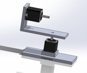
This was one of my first early concept sketches, abandoned due to anticipated balance/torque issues. In this two motor system, I’ve been referring to the lower, vertical motor as motor 1, and the horizontal motor above it as motor 2.
Design 2:
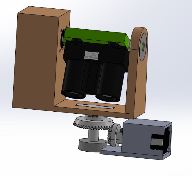
This bulkier design incorporates 2 608 ball bearings and custom bevel gears.
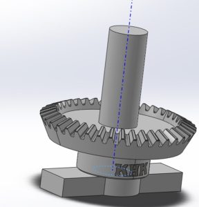
This design started with the intent to incorporate a slip ring for wire management, but that (probably important) element fell to the wayside during the design evolution. I found a pair of bevel gears (https://www.khkgears.us/catalog/product/DB0.8-4020, https://www.khkgears.us/catalog/product/DB0.8-2040) and intended to use them, but conflicting constrictions on bore diameter made prefabricated parts difficult. I took the CAD models provided by KHK and modified them to better suit my design.
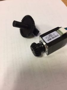
I 3D printed these gears, not really expecting them to work but I was pleasantly surprised. With the few cursory tests I did, the printed gears seemed to mesh well.
This design seemed bulky, lopsided, and difficult to balance, so I abandoned it.
Resolution
Each motor has 200 steps. According to the motor driver documentation, I should be able to operate each motor at 1/32 steps. This will allow for 0.05625°/step rotation (360°/(32 increments/step * 200 steps)). The LiDAR has a max range of 40m. At this rotational fidelity, the LiDAR will subtend an arc of no more than 4 cm between measurements at maximum range (S=θR). At 10 meters, it will measure points less than 1 cm apart. An average room is probably closer to 3 meters wide, allowing for measurements to be taken less than 3mm apart. This should provide an extremely high resolution point cloud.
Compare this to the original servo based prototype with an angular fidelity of ~1°; at 10 meters, each point measured is ~17.45 cm apart, and at 40 meters, this gap becomes nearly 70 cm. Even at 3 meters, measured points are more than 5cm apart.
Redesign (V3)
After getting stuck with the earlier design, I scrapped everything and started fresh again and created a dramatically simplified design. I roughed out two earlier concept designs, but didn’t fabricate either of them. This redesign is the first to actually be printed, but for the sake of my file organization and version history I’m listing it as the 3rd design.
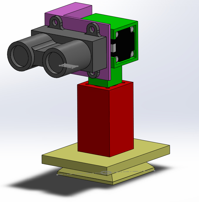
For visual clarity, each component has been given it’s own color.
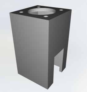
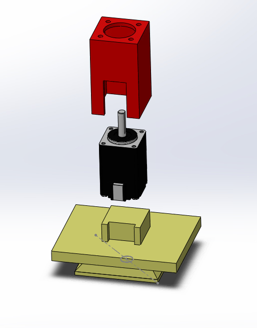
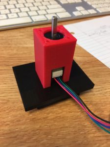
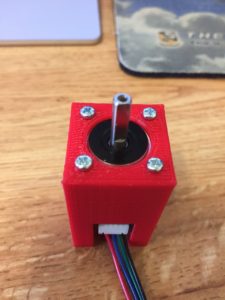
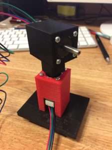
I started with a simple housing for motor 1 with cutouts for the wires, shaft, and screw holes. This housing also serves as a the foundation for motor 2’s mount.
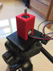
I needed some way to keep this system stable while it moves. I fused motor 1 mount with a modified tripod mount recycled, in part, from the one I designed back in March. Now I’ll be able to test the scanning system from the top of my tripod, giving me some freedom with height and placement in the room.
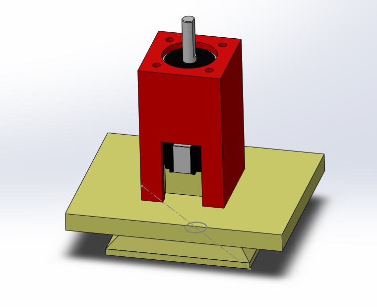
The raised square on the tripod plate interlocks with the motor 1 housing. I designed both parts with slightly wider than necessary tolerances (unsure of how finely they would print). As a result they fit together loosely and not snugly as I had intended. I may adjust the tripod plate and reprint it at some later date and time. The motors are secured with some M2 screws from McMaster.
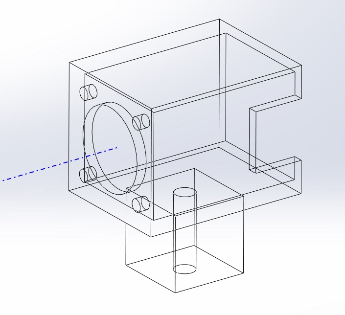
Motor 2’s mount and housing shares the same base design as the Motor 1 mount, with an added column for Motor 1’s shaft.
The bore diameter, although designed to be exactly 4mm printed slightly smaller. A quick spin with a 5/32” drill bit (3.97mm) cleared up the hole, and the motor shaft now fits snugly.
Next up is to print the LiDAR mount, finish the assembly, and start working on wiring!
