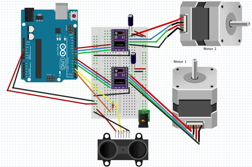
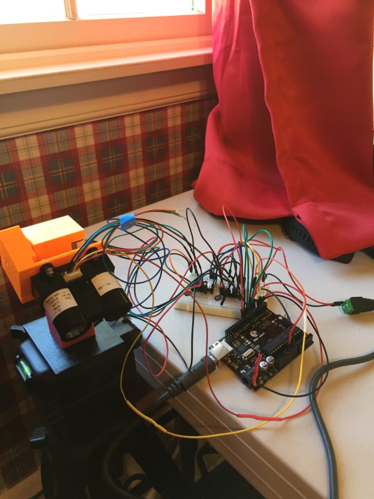
Here’s how the system is wired.
You can access the Fritzing files at http://fritzing.org/projects/lidar-motor-circuit
The 100uF capacitors next to the motor drivers are to protect the driver from voltage spikes, as per the product specs. The Arduino and motors are both powered via USB cables.
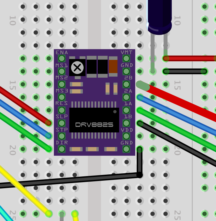
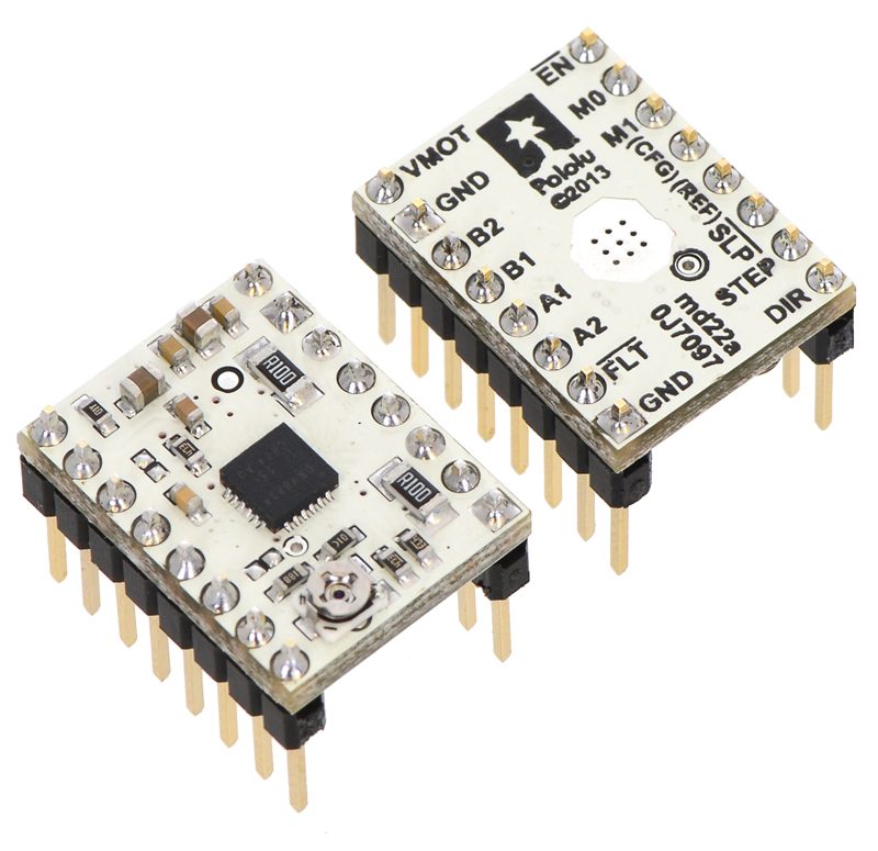
This close up of the motor driver more clearly shows the pinouts.This diagram uses the DRV8825 driver but the project actually uses the DRV8834. I was unable to locate a model fo the DRV8834, so I used the 8825 in the model, as it has the same pinouts.The tiny screw on the driver adjusts the current. It requires incredibly small adjustments. Setting the sleep pin to HIGH turns on the driver.
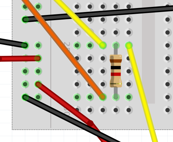
A 1K resistor sits between the trigger and monitor pins for the LIDAR.
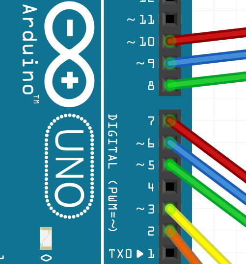
This close up of the Arduino better shows the pins in use.
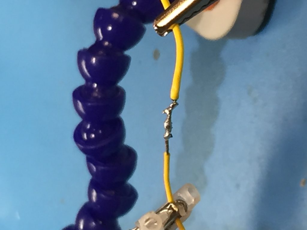
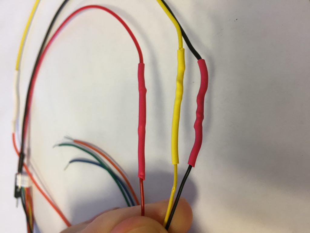
I spliced all the motor and LIDAR wires with male jumper wires to make them longer and easier to plug into the breadboard. The motor cables and LIDAR cable disconnect from their respective components to make this easier.
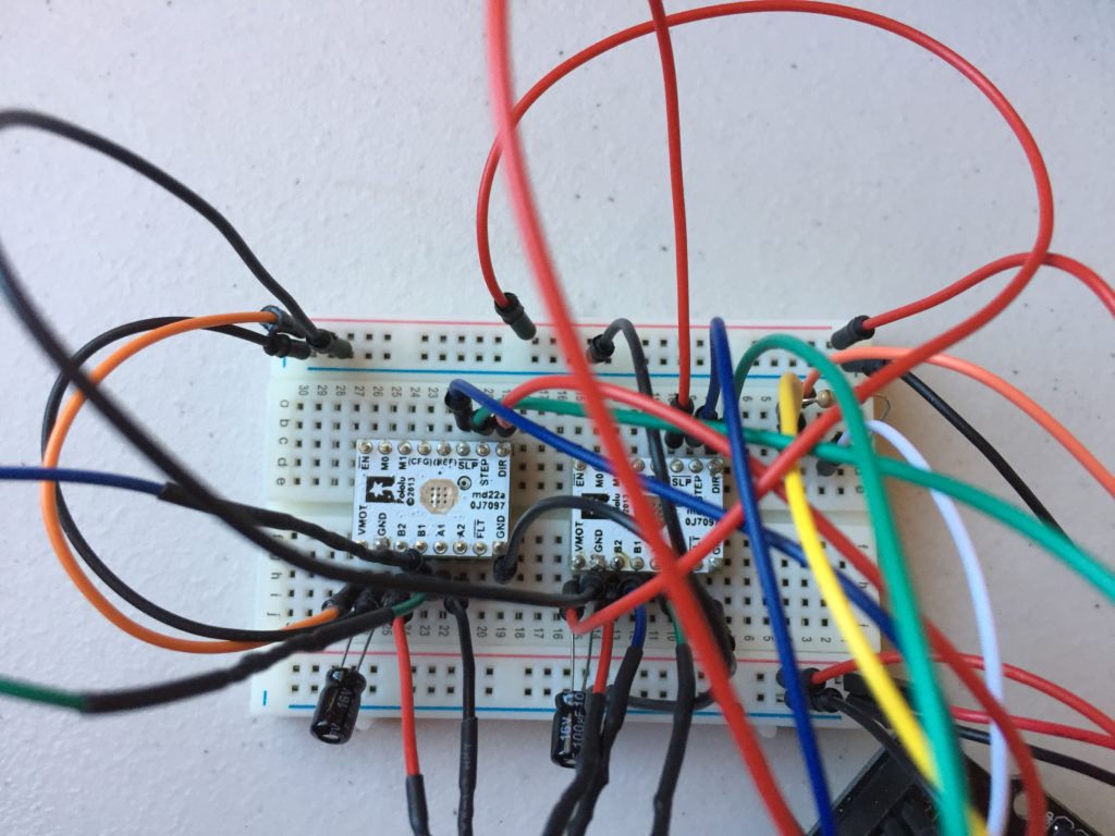
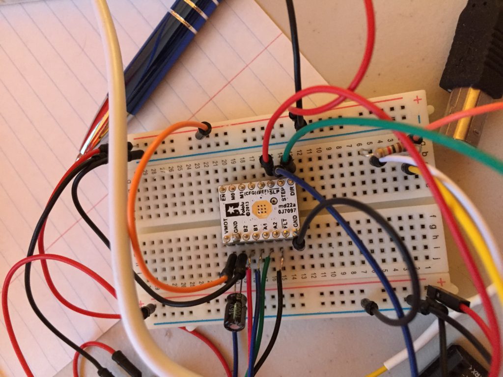
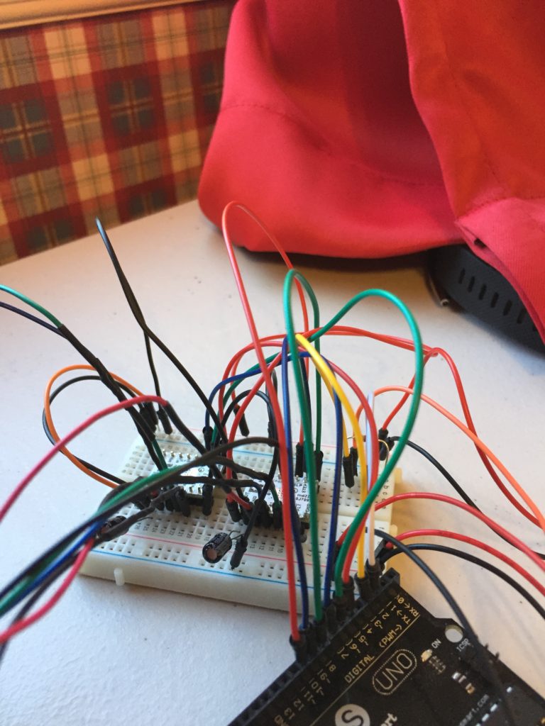
This picture shows the wiring of the motor 1 driver. I later rewired everything to fit on one breadboard, as the diagram above shows.
Note that the pins on the driver can be soldered onto either side. I soldered them this way in order to view the pin labels, but it would have made more sense to solder them on the other side, to allow access to the current limiting screw. The Fritzing wire diagram shows the alternative driver pin configuration.
The wires are much messier in real life. 