The stepper driver recognizes a pulse as a 1 step increment. To test this, I briefly used the Arduino tone() command to make the motor spin.
The code underwent significant trial and error as I learned how to best make it work. I recycled code from one of Arsenio’s previous projects, and then Emery and I rewrote it several times before we got it working. The code is founded on the AccelStepper Arduino library, which allows us to specify positions for the motor to turn to. Stepper motors don’t have an absolute zero position; rather, the “0” position is whatever position the motor is in when the Arduino boots. I found it necessary to manually set the motors in particular positions when they started to avoid wire entanglement. The motors only know their position relative to where they start – the code cannot account for if they slip and change positions. The full code for this project is accessible on Github at https://github.com/BrianBock/LiDAR.
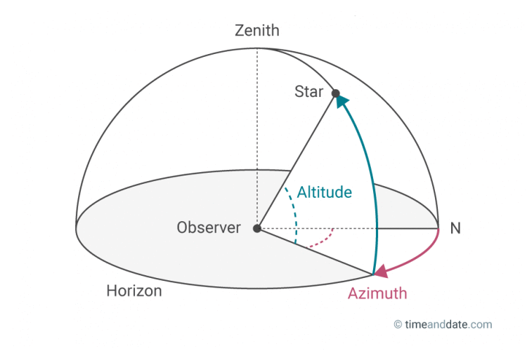
As per the above diagram, motor 1 is the Azimuth motor (Azi) and motor 2 is the altitude motor (Alti). This convention is used throughout all of the code.
Fundamentally, this is how the program works:
Azi increments from position 0-800 and takes a measurement at each step.
Alti increments 1.
Azi moves from 800-0 (in the other direction) and takes a measurement at each step.
Alti increments 1.
This repeats until Alti reaches its max position (~266). For wire management, the Azi motor can’t exceed position 800. A redesigned system with a slip ring would mitigate this and allow the motor to spin continuously in just one direction.
For now, the system runs at it’s default ¼ step. This means that for each of the 200 steps inside the motor, the driver can increment 4 times, requiring 800 increments to complete a full 360 revolution. Theoretically the drivers support up to 1/32 step, and I plan that future versions of this program will support such higher resolutions.
The Arduino outputs in the following format:
“Azi Position, Alti Position, Distance”
Both positions are integers representing the number of increments since 0, and the distance is measured by the LIDAR in centimeters. This format should lend itself easily to being saved as a CSV. I may use CoolTerm to save the Serial monitor output.
The conversion from this raw data to coordinate points is relatively simple and requires a little bit of trigonometry. Note that 360°/800 steps = 0.45°/step. I built an Excel spreadsheet to handle all calculations, so the following formulas are formatted for Excel.
x=distance*cos(RADIANS(.45*azi))
y=distance*sin(RADIANS(.45*azi))
z=distance*sin(RADIANS(.45*alti))
***NOTE (from the future): These formulas are totally wrong. I’m keeping them here for posterity. Check out this newer post for actually correct information.***
Currently this conversion would be done externally through Excel. I’m hesitant to embed this functionality onto the Arduino because I don’t want to slow the system down, especially as I try to speed it up and run at higher microstep resolutions. I may experiment with this in the future and see if this hesitancy is misplaced.
As I finalized the software, I discovered that motor 2 (alti) never seemed to move. After some tests, I discovered that the motor does not have sufficient torque to lift the LIDAR rig from the starting position. To correct this, I redesigned the LIDAR mount to include a counterweight.
This video shows the system running. This is early into the run, so the Alti motor hasn’t lifted appreciably.
To verify the functionality of the redesigned mount, I created a modified program to just run the Alti motor. This test can be seen in the video below:
The added counterweight effectively balances the weight of the LiDAR.
I spent some time experimenting with delays to see how fast the system could run. One cycle is a full revolution of the Azi motor from position 0-800 in one direction. The time for one cycle multiplied by 266 (the number of cycles before Alti reaches the top and the program finishes) produces an approximate run time for the system.
With the original 15 millisecond delay, it took each cycle about ~15.5 seconds, resulting in a run time of ~4123 seconds = 68.7 minutes to map a room. This is prohibitively slow, so I slowly worked down this delay and tested all the way down to 2ms. The system runs much faster – about 4.5 seconds/cycle, yielding a much more reasonable 20 minute scan time.
I nearly completed one full test of the entire system working before the constant wire tugging yanked the Arduino and breadboard off my desk and one of the wires broke. I’m going to resplice the LIDAR and Motor wires to make them longer and then I’ll be ready for my first full scan.

