With the lengthened wires, I was ready to start scanning! I visualized the point clouds with CloudCompare.
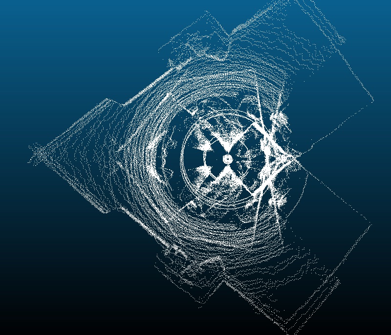
The equations listed in my previous post are completely wrong. I did several full scans of my room and tested them against those equations. None of them produced a point cloud that even resembled any feature of the space.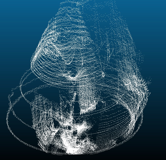
 I had forgotten about spherical coordinates, and had tried to resolve the trigonometry on two orthogonal planes, which does not work. With a little bit of work, the system output can be expressed in spherical coordinates (r, θ, Φ), which can then be converted to rectangular coordinates (x,y,z). Fortunately, this is fairly straightforward.
http://keisan.casio.com/exec/system/1359534351
As previously mentioned, the code outputs “Azi Position, Alti Position, Distance”. By multiplying the current Azi position by 0.45, I get the angle that the Azi motor has traversed relative to it’s zero. Remember that the system is running at ¼ step and has 200 steps so each increment is .45 degrees (360°/800 increments=0.45 degrees/increment). This angle is Theta (θ) in the diagram and the equations on that page.
The same math works for the Alit motor, but with a few modifications. The Alti motor moves in the opposite direction as phi(Φ), so we’ll introduce a new variable alpha(α) to represent its movement, and define Φ=90-α. Following the same steps as the Azi motor, α=Alti*.45.
So we have:
Φ=90-(Alti*0.45)
θ=Azi*.45
x=r*sinΦ*cosθ
y=r*sinΦ*sinθ
z=r*cosΦ
Where r=distance measured by the LIDAR in centimeters
I encountered issues with each trial scan as I experimented with the math and code. At one point, I reversed the direction of the Azi motor to match the direction of theta. Now it goes CCW from 0-800 and then CW from 800 back to 0.
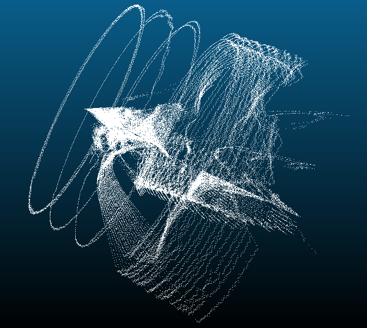
It occured to me that Alti does not start at any traditional axis (straight down or horizontal). Rather it starts at ~60 degrees =~133 steps from the straight down position. I tried offsetting the Alti values by 133 steps in both directions. The results were visually interesting, but continued to bare no resemblance to my room. I then tried compensating to the horizontal – it starts about 30 degrees below the horizontal -> 30/.45=66.66 -> NewAlti=Alti-66. With this setup, Alti’s max becomes 200 steps = 90 degrees, which should’ve worked out for the phi calculations, but was still a mess. After experimenting with these compensators for a while, I realized that I had inadvertently changed the output of the Arduino as the Azi motor moved when I reversed it. Instead of Azi counting from 0 to 800 and then back down to zero, it counted up to 800 and then restarted it’s counter at zero. The result was a strange mirroring effect that made the scans seem almost symmetrical.
As soon as I made this correction and did another scan, I was thrilled to see the point cloud actually align with the room I scanned.
So now:
AltiCorrected=Alti-67
Φ=90+(AltiCorrected*0.45)
θ=Azi*.45
x=r*sinΦ*cosθ
y=r*sinΦ*sinθ
z=r*cosΦ
Make sure to convert the angles to radians before inputting them in the trig functions (or otherwise use the trig functions in degree mode).
I’ve been testing the equations in a massive Excel spreadsheet. I copy the entire output of the Serial monitor and then paste it into predefined columns in the template, and then it does all the necessary math. Now that I know it works, I can work on automating a more streamlined method.
Serial Monitor does not log when my computer screen sleeps. I didn’t realize this at first and ended up with several scans missing significant sections of data. Caffeine for Mac is an easy way to keep the computer awake and avoid this issue.
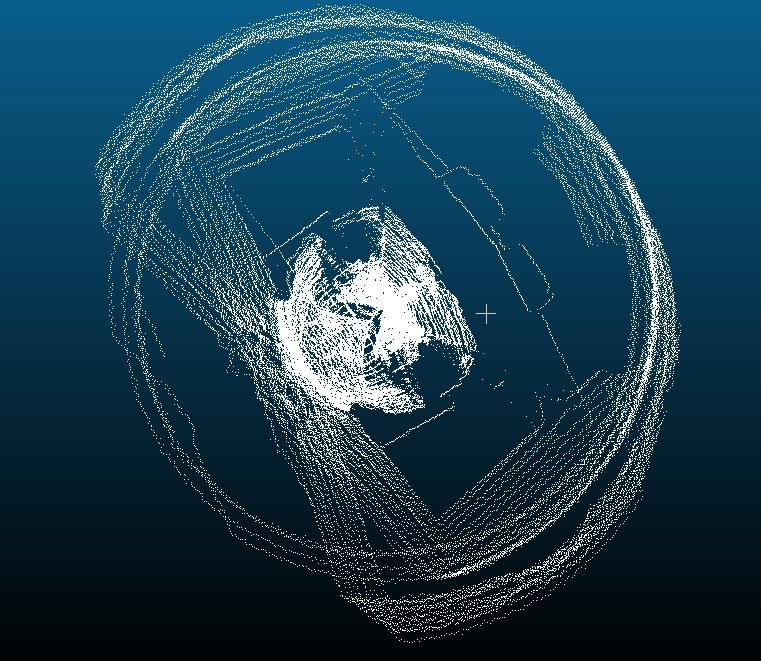
Azi’s zero seems to slide as it scans – as a result, the “walls” tend to have diagonal, sloping edges. I still haven’t reprinted the motor 2 housing – that might be the issue. It’s kind of tricky to get a picture of the point cloud at an angle that makes it clear – the visualization is much easier to see with some movement. I made a short video showcasing the most complete point cloud I’ve gotten so far.
This point cloud is actually a mirrored representation of my space – I’ll have to play around with the calculations some more to get the “x” axis (*I’m just calling it x, I don’t actually know which way it’s flipped relative to the points yet) going the other direction.