I realized after finishing the board that I used the Arduino’s analog and power pins purely for structural support without any intent to make them usable. I used pin headers to connect those pins to my shield. I should’ve instead soldered on a 6 pin and 8 pin stackable header to regain access and use of those pins.
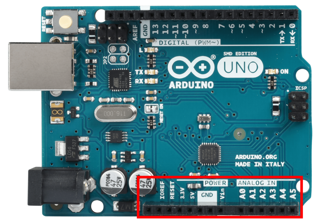
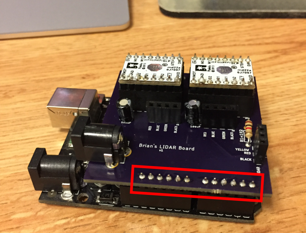
I don’t actually need any of those pins for anything right now, but it’d be good to have them accessible for the sake of future expansion and versatility. If I were going get another board printed, I would label all of these pins on the board for ease of use. For whatever reason, I only designed this side of the board with 12 holes instead of 14, so two more pin holes would also need to be added. I don’t think these modifications alone warrant the cost of another three boards (~$22), so it will probably stay as is for now.
You remember this chart about microstep resolutions.
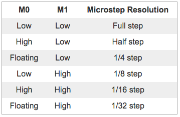
I had previously been running both drivers at their default ¼ step. When I designed the shield, I added wires for the M0 and M1 pins for both drivers with the intent of later working up to higher resolutions. Now the M0 pin is connected to the Arduino, which can’t do floating, so I’m unfortunately locked out of the ¼ resolution. I modified the code to run at ⅛ step and this is where I started running into problems. At higher step resolutions, the motors run much hotter. After some test runs, the alignment of motor 2 slipped, and I stopped the scan to evaluate why. I discovered that the motors, in addition to being very hot to the touch, were getting hot enough to begin making the PLA motor housings slightly pliable. Motor 2’s housing (around the shaft), deformed enough to become misaligned (although not enough to be readily visible in person or in a photo). I need to redesign the housing for all three components with heat dissipation in mind and then re-print them. The current designs are fully encapsulating insulation with nowhere for the waste heat to go. I’ll be looking into getting heat sinks for both motors.
As a consideration for future versions of the Arduino shield, I’d like to add an SPST switch between each M0 driver pin and corresponding board pin to enable/disable floating. I can’t imagine a scenario where I would run the motors at different resolutions (I think that would just complicate things) so alternatively, a single DPST switch would be sufficient and be more space conservative on the compact board.
Going forward, I plan on incorporating Processing for better data collection. I plan to have Processing intake the serial output from the Arduino, do all the coordinate calculations, and then save the coordinates as a CSV. I may also build in options for choosing the operating resolution when the scan is started.