The Idea
In the last week of September, I started this project. While not yet done, this has so far been a much quicker project than most on my website. This project was inspired by my younger cousin, who suggested I make a Halloween themed animatronic – a spooky Halloween decoration with moving eyes. I realized I could build this without too much difficulty, and then add an additional layer spooky factor – if I incorporated a Raspberry Pi and some facial detection, I could have the eyes turn to track human faces.
I started with a quick whiteboard sketch outlining what would soon become a rack and pinion based design.
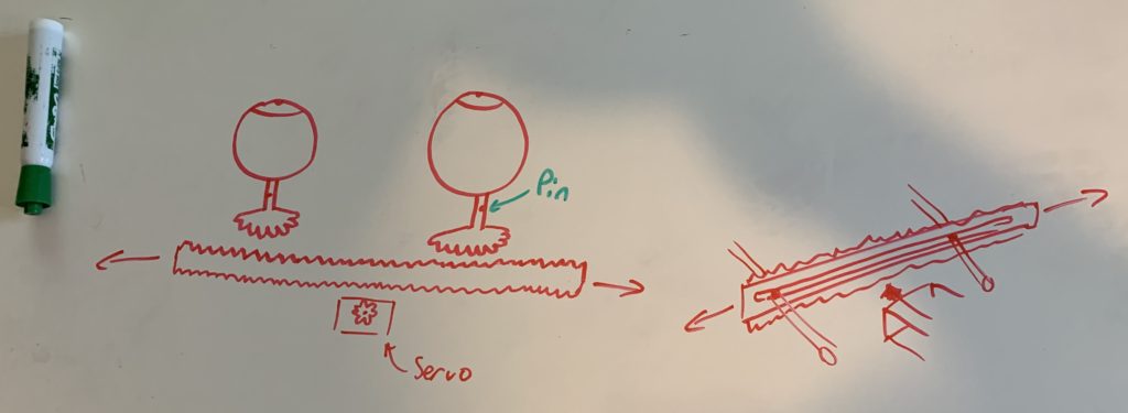
After a few minutes looking at this design, I realized I needed the axis of rotation for each eye to be coincident with its own center, and not offset as drawn. Additionally, there was no need to have a two sided rack, as the servo could just as easily (more easily, actually) live on the same side as the eyes. In a few hours, I modeled (in SolidWorks) a rack and pinion assembly which had two eyes actuated in unison via a servo. I also learned how to create a motion study in SolidWorks and then export it to SolidWorks Visualize, which can utilize GPU power to expedite the render.
The system is comprised of a few parts (most 3D printed). Two spherical eyes sit atop square extrusions on round shafts. These shafts have a pinion gear embedded, and the bottom interfaces with the base (green) with a rounded end. A rack, actuated by a servo (with a matching pinion gear) slides left/right to rotate the eyes. I modeled the eyes to be about the same size as average human eyeballs (and, in doing so, I discovered that if you Google “human eyeball dimensions”, Google prominently offers you lots of images of human eyeballs outside of humans. *shudder* No thanks)
I recent purchased an Original Prusa Mini 3D printer. This was the first project to begin to utilize this new in house resource. Satisfied with the first iteration of this model, I began printing parts. It took some trial and error to nail down the printer’s tuning to produce quality prints.
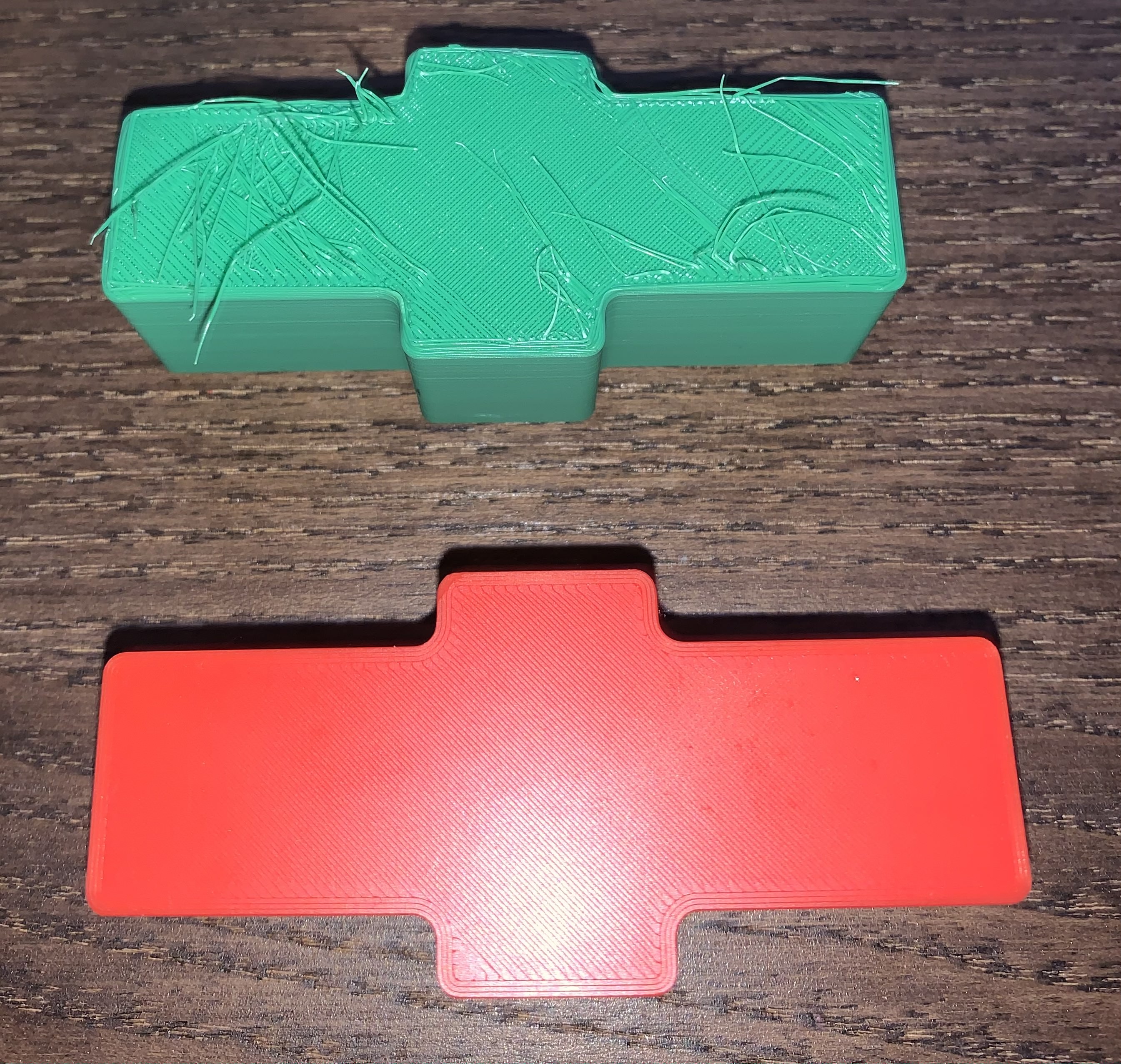
The shafts the eyes are mounted on (ending on one end in a small square extrusion and the other in a rounded edge) proved challenging to print, due to their small surface area (for build plate adhesion) and their tall length (long moment arm for knocking over). I found the best orientation was upside down (with the flat square eye extrusion on the build plate) with brim and support everywhere. Again, it took a few tries to get these parts to print cleanly. Below is a video demonstrating the rack and pinion action of the assembly. In this early print, the parts fit snuggly and required a fair bit of torque to turn (later versions fit better and rotate much more easily).
The full assembly underwent a number of minor revisions, improving the appearance (with filets), layout, and part interface fit.
LEDs
The eyes would definitely be spookier if they glowed, and even more so if the eyes could change colors. I ordered some RGB LEDs from Amazon and tested them quickly on a breadboard.
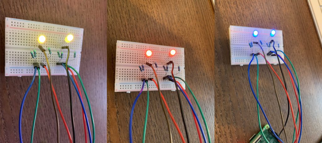
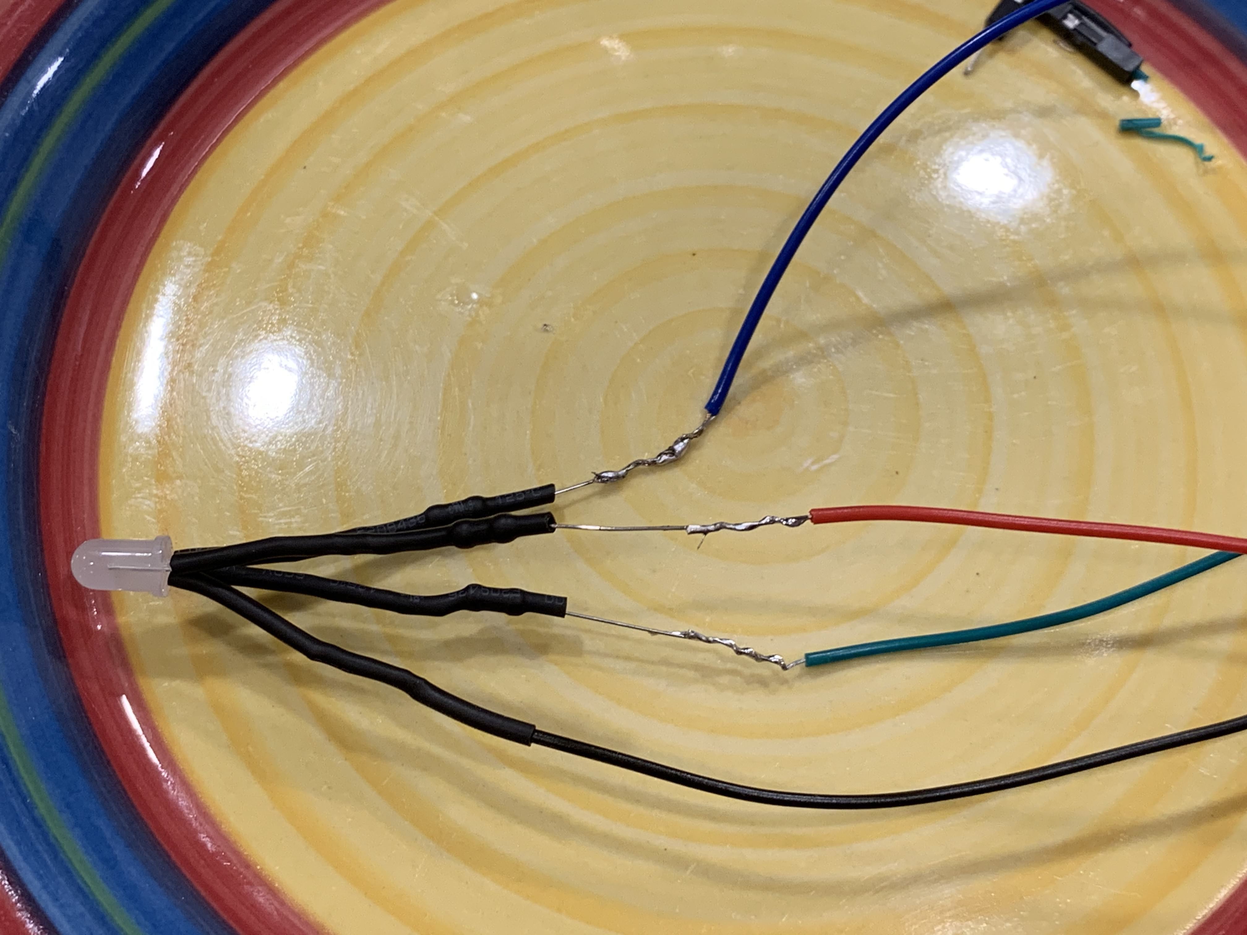
After I was satisfied with the color range (and the resistors provided by the manufacturer), I began soldering resistors to the LED leads.
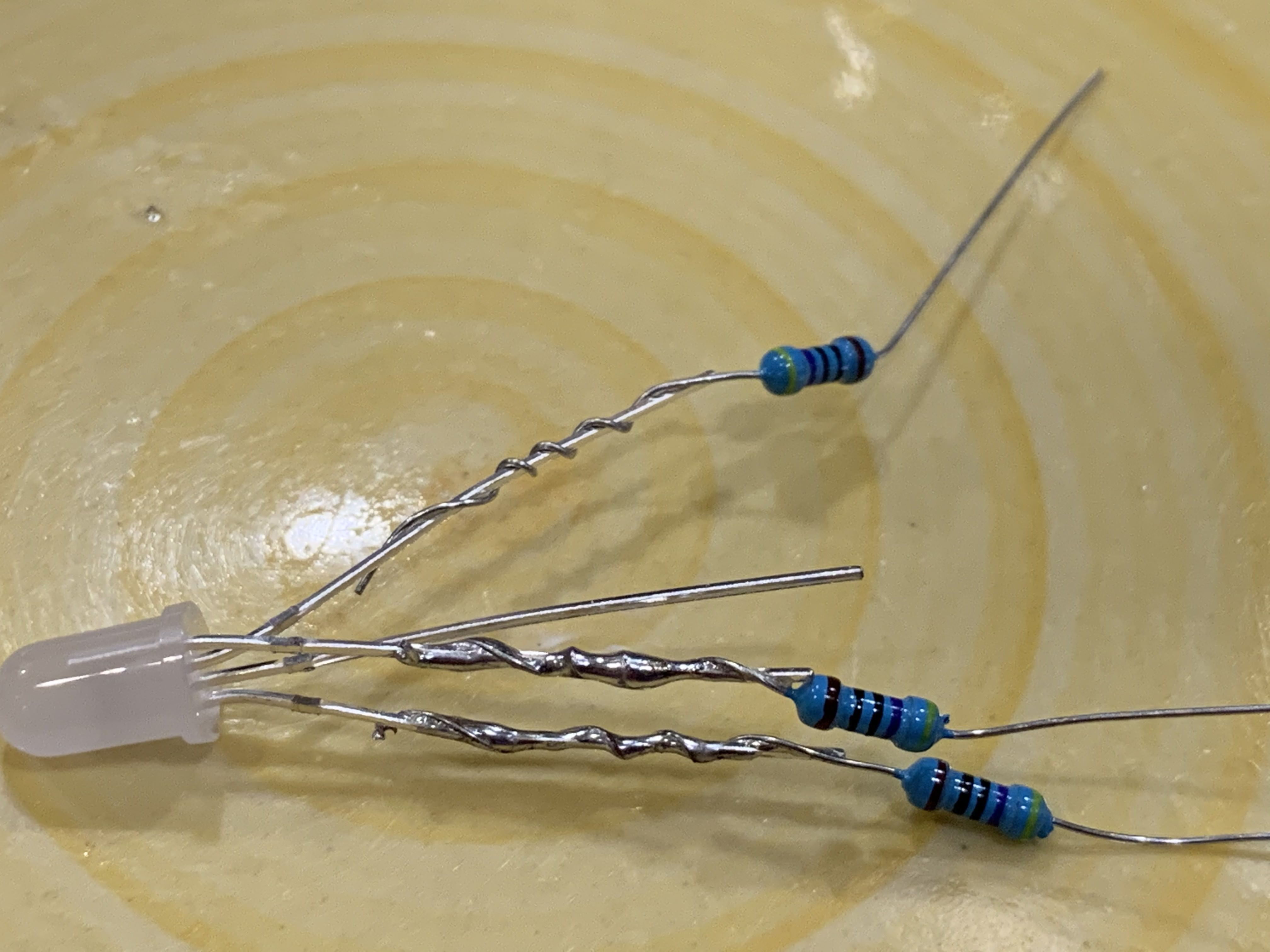
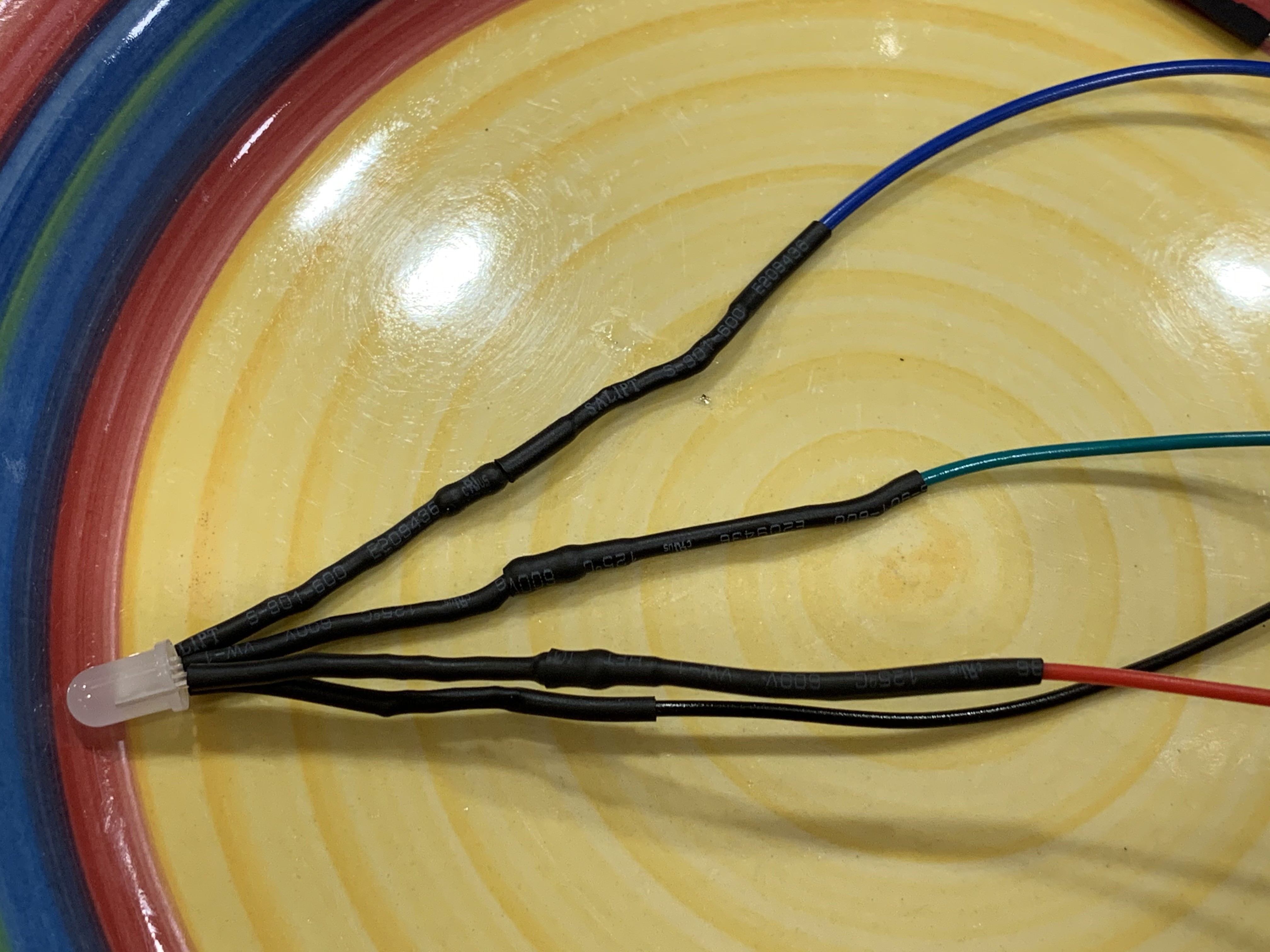
I knew I wanted to connect these LED/resistor assemblies directly to the Pi, without a breadboard in between. I therefore needed female jumper wires spliced to the end of the resistor leads. To protect the soldered resistors (both physically and electrically), I slid some heat shrink wrap tubing over the resistors and (additional tubing) over the jumper wires. After splicing the wires to the leads and soldering each connection, I melted the heat shrink tubing over the resistors, and slid the other tubing over the spliced connection.
Skull
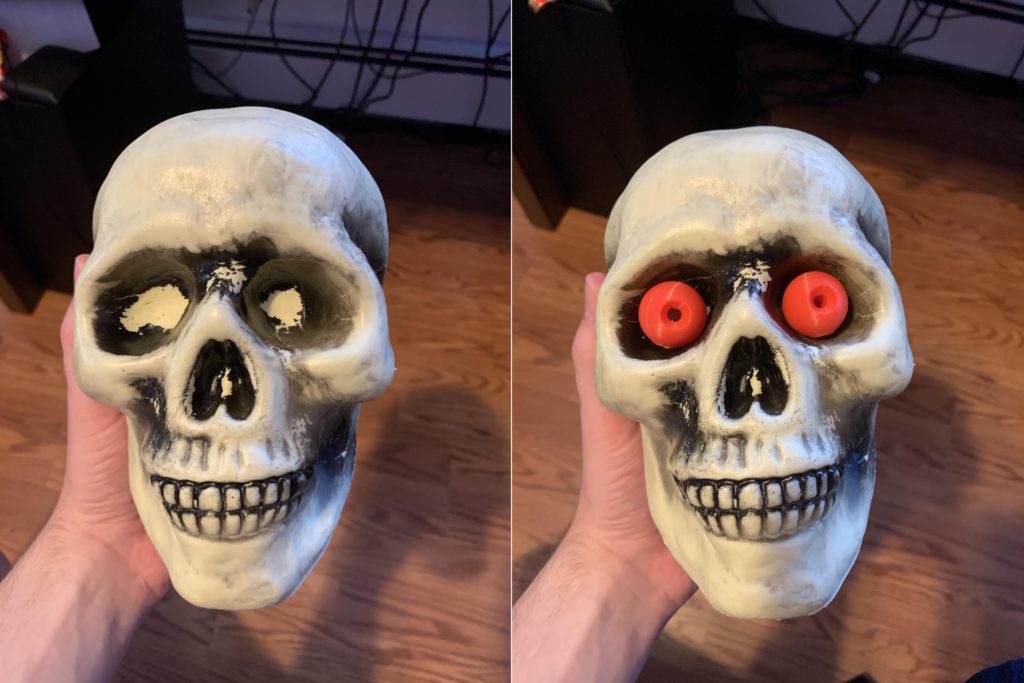
I found an old plastic skull in the attic (part of a previous Halloween lawn decoration). The eyes (which I had sized to be comparable to human eye balls), fit nicely.
More to come on this project soon!
Pingback: Skull Modification and Redesign – Brian's Portfolio