I ordered a servo, a 4xAA battery pack, and some more wires on Amazon.
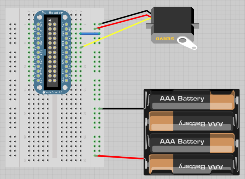
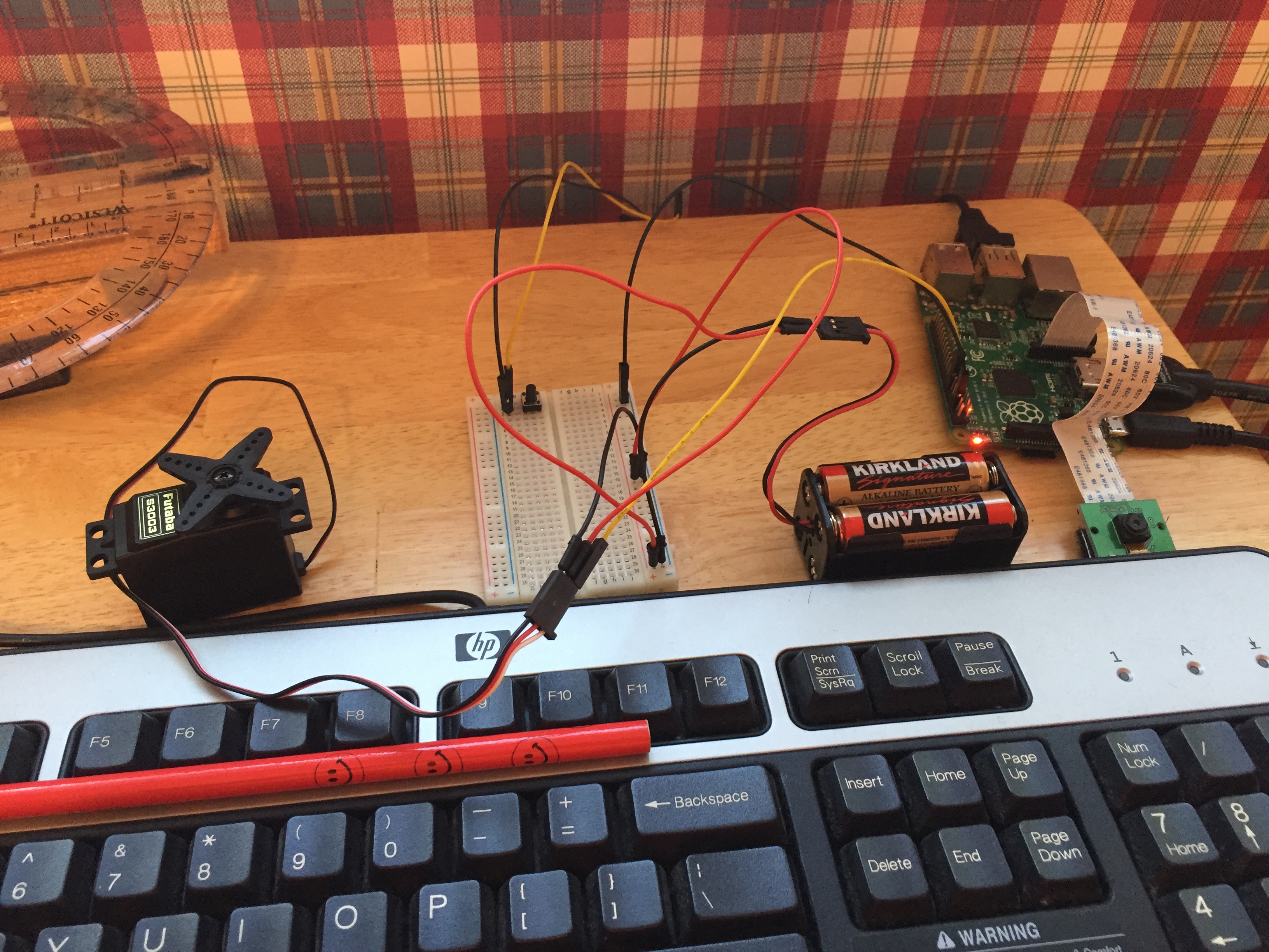
Following the directions from Adafruit’s Pi servo tutorial, I connected the servo, battery pack and Pi (as shown in the photo above).
This is when things got a lot more complicated than I expected. I spent the better part of a day reading up on how to control a servo(s) from a Raspberry Pi, and it is not nearly as simple as I had hoped. I’m going to try to summarize what I’ve learned and include helpful links incase anyone ever wants to duplicate any part of this project.
Servos: The Basics
The first step in controlling something is understanding how it works. Fortunately, there are many sites that provide detailed explanations, including Adafruit. The position of the servo motor is set by the length of a pulse. The servo expects to receive a pulse roughly every 20 milliseconds. If that pulse is high for 1 millisecond, then the servo angle will be zero, if it is 1.5 milliseconds, then it will be at its centre position and if it is 2 milliseconds it will be at 180 degrees.

Simple GUI Servo Control
The easiest way that I’ve found to control a servo through the Pi is via O’Rielly’s servo control script.
fromTkinterimport*importRPi.GPIOasGPIOimporttimeGPIO.setmode(GPIO.BCM)GPIO.setup(18,GPIO.OUT)pwm=GPIO.PWM(18,100)pwm.start(5)classApp:def__init__(self,master):frame=Frame(master)frame.pack()scale=Scale(frame,from_=0,to=180,orient=HORIZONTAL,command=self.update)scale.grid(row=0)defupdate(self,angle):duty=float(angle)/10.0+2.5pwm.ChangeDutyCycle(duty)root=Tk()root.wm_title('Servo Control')app=App(root)root.geometry("200x50+0+0")root.mainloop()
This provides a simple slider interface through which you can control the position of the servo. Note that most servos do not have continuous rotation, and therefore can only turn up to 180°. This rotative limit is actually beneficial for this project as I won’t need to worry about the camera wires getting twisted. Below is a brief video of my first test of this slider.
There are a few problems with this setup. Most importantly, it only works through the GUI, so this technique is not transferrable to the rest of this project. The script constantly tells the servo what position it should be in (even if it hasn’t changed), resulting in the jitters seen in the video. This shakiness will probably result in blurry photos.I need to be able to tell the servo to turn to a position (likely 45°), and then stop. The Pi would handle the picture taking and then tell the servo to move again.
Occidentalis

It seems that some time ago, there was a fully Raspberry Pi OS called Occidentalis (Latin for Black Raspberry) which offered wonderful PWM support, which is crucial to controlling servos. Unfortunately, it has subsequently been discontinued as its own operating system. Many online tutorials and guides still point to this program, and it took a while for me to find one that didn’t. The software engineers behind Occidentalis decided it was easier to offer a stand alone program than to try to keep up with the many revisions of Raspbian and Raspberry Pi. They offer a program called Pi Finder, which is designed to find a Pi on your network, and then give you the ability to remotely install software. Unfortunately, I have been unable to make this “Bootstrap” process work, which may in part be attributed to how my Pi is configured on my home network. My desk lacks nearby functional network jacks, so the Pi is connected to my Mac, which is sharing its Wifi connection over ethernet. As a result, the Pi has a 192 IP address instead of a 10. IP address, and the computer had difficulty connecting to it. Fortunately, however, Adafruit has an excellent guide on adding repositories and installing packages, and both occi and Occidentialis are available as packages from the Adafruit repository. This program needs more of my attention, as I have not yet figured out how to make it do what I need it to do. Once I get it working, I should be able to follow this Adafruit tutorial to control the servo.
I2C PWM Boards
Adafruit offers a variety of add-on boards for the Pi designed specifically for PWM control. I’m told that these boards are very easy to use and provide excellent control as well as stability. The Adafruit 16-Channel PWM / Servo HAT would probably be perfect for this project, and supports up to 992 servos! It requires its own power supply, which although fine for testing, is something else to keep in mind when this project needs to become portable.
ServoBlaster
ServoBlaster is another project designed to provide servo control from a Pi, but from what I’ve read online, it is not a very stable solution. [UPDATE] With some effort, I got ServoBlaster working! So far it seems to work well.
To install ServoBlaster, run this command from the Pi in Terminal. This copies the files to the Pi.
git clone https://github.com/richardghirst/PiBitsFrom /home/pi/PiBits/ServoBlaster/user, run the following:
pi@raspberrypi:~/PiBits/ServoBlaster/user $ make servodThis installs servod.
./servod --helpReveals the documentation and help page
sudo ./servodReveals information about the Pi and what name/number corresponds to each pin.
The following command can now be sent to tell the servo to move.
pi@raspberrypi:~/PiBits/ServoBlaster/user $ sudo echo P1-12=00% > /dev/servoblasterP1-12 specifies the pin the servo is connected to (GPIO18). The two digits before the % represent the percentage turn from position 0. This value can also be input in steps or microseconds, but I think percentage is the easiest to understand and use. This can also be increased incrementally with a + or – sign before the number (Ex: +10% adds 10% to the previous value).