It’s been a little while since I last updated this blog, and I’ve made considerable progress in that time.
Hardware Updates and Testing
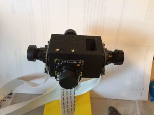
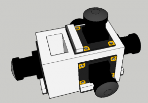
I assembled the square camera mount with a camera on every side except the top and bottom. (There is no room for a camera on the bottom.) I used this to take several panoramas to test the field of view. They worked really well. There was ample overlap in the horizontal direction and the vertical direction covered more than I expected it to, but there was still a sizable hole in the image directly above the viewer’s head.
It took some time to figure out how to view the panoramas with my Google cardboard. I tried several different applications with varied success. More information on this is available below.
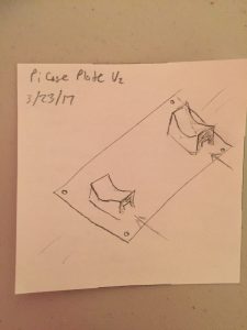
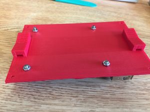
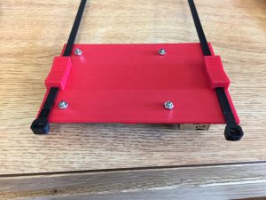
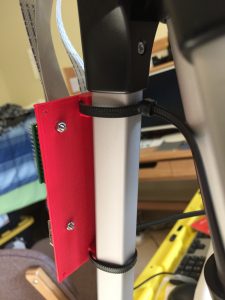
The tripod brace mounting system I had previously designed had some flaws. It didn’t hold as tightly as I needed to, and slid down the tripod, even when tightly packed with old bike tube. Over spring break I designed a new method of attaching the case that utilized zipties.
Unlike the previous revision, this prototype had screw holes to mount the Pi, adding stability to the system. I got some new screws and nuts from McMaster for this purpose, and they work well.
Soldering Pins onto the Arducam Multiplexers
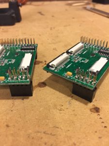
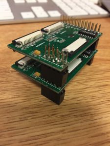
I bought a second multiplexer so that I could integrate a 5th camera. Out of the box, both multiplexers came with a 10 pin header that was not attached. It was clear at a glance where it needed to be connected (the matching 10 holes on one side) but why it needed to be connected wasn’t initially clear. I’m not a fan of unnecessary soldering, so I hadn’t installed these pins when I started. For my 4 camera tests, the multiplexer worked fine. When I connected the second multiplexer, I couldn’t get any data from the 5th camera. Only then did I realize the purpose of these pins – they serve as a data passthrough for the upper boards. After a soldering attempt that took WAY longer than it should (over an hour and a half), I finished soldering these pins on both boards.
It isn’t pretty but I was hopeful that it would work anyway. It didn’t. With the 2nd multiplexer attached, none of the cameras worked at all. They all have a little light that turns on when any of them are in use. No lights turned on with the 2nd multiplexer connected. I briefly panicked and worried that I had shorted my entire project. Fortunately, when I removed the second multiplexer, the first four cameras resumed working without issue. I will regrettably likely need to redo the soldering on both boards to make them work together.
Important side note: the Pi MUST be off when you attach or detach a camera or multiplexer. If you connect or disconnect one while the Pi is on, it will reboot.
How to view 360 Photos on Google Cardboard
Take your panorama. You can do this within the Google Cardboard Camera app on iPhone or Android. Using the camera within the app is by far the most straightforward way. If you are taking the pictures externally, follow the rest of the steps below.
I used Hugin to stitch together the photos I had taken into a panorama. Download Google’s StreetView (iPhone or Android)
StreetView requires that photos are at least 5300×2650 and in a 2:1 ratio. If your panorama isn’t (and it probably won’t be), open your favorite image editor (I’m a fan of Photoshop) and add black bars at the top and bottom until you have the right size. Save the photo as a .jpg (you may have success with other file types, I didn’t try). Transfer it to your phone.
Open StreetView. Tap the orange camera icon in the corner. Tap “Import 360 Photos”. Navigate to where you saved your photo and choose it. Click Import. Back on the main page, in the Private tab you’ll now see your panorama (you may need to scroll down). Tap to select the panorama. You can use your thumb to navigate around the photo, or tap to reveal the cardboard icon in the corner. Pop your phone into your cardboard and enjoy your view!
Automated Panorama Stitching through Hugin on a Raspberry Pi
I finally figured out how to run Hugin on the Raspberry Pi. Hugin and many of its components have a long and convoluted history of developers and mixed documentation. There’s a lot of redundancy and incompleteness. I read through over 50 miscellaneous webpages today as I tried to piece together what I need to do. It is, to be succinct, quite a complicated mess. Fortunately, after all of that work, the end result is actually quite simple. I’ll try my best to outline the process clearly here so that anyone reading this can figure it out in the future.
It turns out that Hugin’s command line tools are available in Debian. Raspbian, the operating system that runs the Raspberry Pi, is a variant of Debian. I was worried that the differences between the two OS’s might be prohibitive, but they actually are not in this case.
On your Pi, navigate to: https://packages.debian.org/jessie/hugin-tools. This page is the repository for Hugin tools in Debian. Scroll down to the bottom and choose armhf. (I tried a few others but this was the only one that worked.) Pick your region and favorite downloader. I used the ftp.us.debian.org/debian link without issue. When it finishes, launch the installer. It may take a few minutes to finish. When it completes, you should have access to the commands listed on that Debian page. Open Terminal and test one of them. Don’t worry about images or parameters or anything else – just make sure that you have the commands.
Next you need to install enblend: sudo apt-get install enblend
To simplify this endeavor for anyone else who wants to try, I created a scripted installer that will handle all of these steps for you. It includes a time-lapse script, photo taking script, stitching script, and a sample template and sample photos. It’s well documented and available on Github at: https://github.com/BrianBock/360-camera
On your computer, build a template in Hugin. This can be done the same way you’d make a panorama. When you have it perfect, save the project as template.pto and copy it to the Pi.
run-timelapse.sh creates a new folder inside /home/pi/Time-Lapses/ with the current date and time, and then kicks off ‘take-pictures.py’ and ‘stitch-pictures.py’.
‘take-pictures.py’ iterates through each camera and takes a photo. It takes about 3 seconds per camera to take a picture. The command prompt window will update you with it’s progress. Each photo is saved as capture_1.jpg, capture_2.jpg…capture_4.jpg in a round_# folder. Round refers to how many photosets have been taken. The first round is Round 1.
This starts stitch-pictures.py, which uses Hugin’s command line tools and the template you created to create a panorama. This produces panoramas very consistently. Any defects or tears present in the template will be propagated to any future panoramas, which is why it’s so important to make the template as perfect as possible. With this setup, Hugin does NOT calculate control points to find the overlap in the images, which saves time and processing power, and means you don’t need to worry about people moving between cameras’ views or other issues that might cause stitching problems. On the other hand, Hugin is basically running blind. If your photos don’t line up nicely, it won’t care and you’ll get a funky panorama.
The stitching program creates a series of temporary tifs in the Software folder with the proper distortions. It uses these to create the final panorama tif for this photoset, titled round#.tif. This large image is then copied to the folder labeled “tifs” within /home/pi/Time-Lapses/TodaysDateTime/. The temporary tifs are then auto-deleted. When the round is finished, the window will notify you of its completion and how long it took. On a Raspberry Pi 3, my preliminary tests averaged about 90 seconds/round. If you’d like to change the photo frequency, open ‘run-timelapse.sh’ in your favorite editor and change the INTERVAL at the top. Originally I made it default to wait 1 minute between rounds, but then I made the Interval dynamic. It subtracts the run time from the desired interval to get a delay, so that photos are taken at consistent intervals (2 min).
I’m really pleased with how well this works. It’s easy to start and can run entirely independently. The system has verbose output so I can easily tell what it’s doing and where it gets stuck, if an issue occurs. The end result is an organized folder with all of the stitched frames from the time-lapse, which will be imported into Premiere to be made into a video.
Power Requirements
I used my USB power meter to monitor the draw of this system while it ran. It holds steady at 5.2V but the amperage fluctuates based on what the Pi is doing. While dormant, the Pi uses 5.2V and ~.25A. Peak current was around .65A. To be safe, I’m rounding the power requirements up to 1A. I found a 20Ah battery on Amazon that is well reviewed. At 1A power consumption, that battery will power the system for 20 hours, which is more than sufficient for my purposes. It should actually power everything for closer to 30 hours (20Ah/.65A). I did a video capture of the script running and overlaid the power monitor so it’s easy to see what processes are most power intensive – you can watch it here. Amazon says the battery should be arriving tomorrow, so soon I’ll be able to take some outdoor time-lapses.
What’s next?
I need to redesign and reprint the Pi case to allow room for the second multiplexer. This should be fairly easy and quick to produce. As previously mentioned, I need to fix the second multiplexer so that I can use the 5th camera. Once all 5 cameras work, I’ll need to create a new template file for the Pi to use.
I might work on a light platform for the system to post status updates to.
I can begin outdoor testing as soon as the battery arrives and I have a nice weather day.
