In my preliminary tests, I quickly discovered that the 3D printed motor shaft hole on the motor 2 mount (connecting motor 1 and 2) isn’t snug enough. When Motor 1 spins, any resistance at all frees the upper components, and the lower motor spins without them. While I haven’t tested it, it stands to reason that the LiDAR mount (with the same hole dimensions) would have the same problem. After some consideration and thought, I redesigned the two components with holes for a hex nut and a set screw.
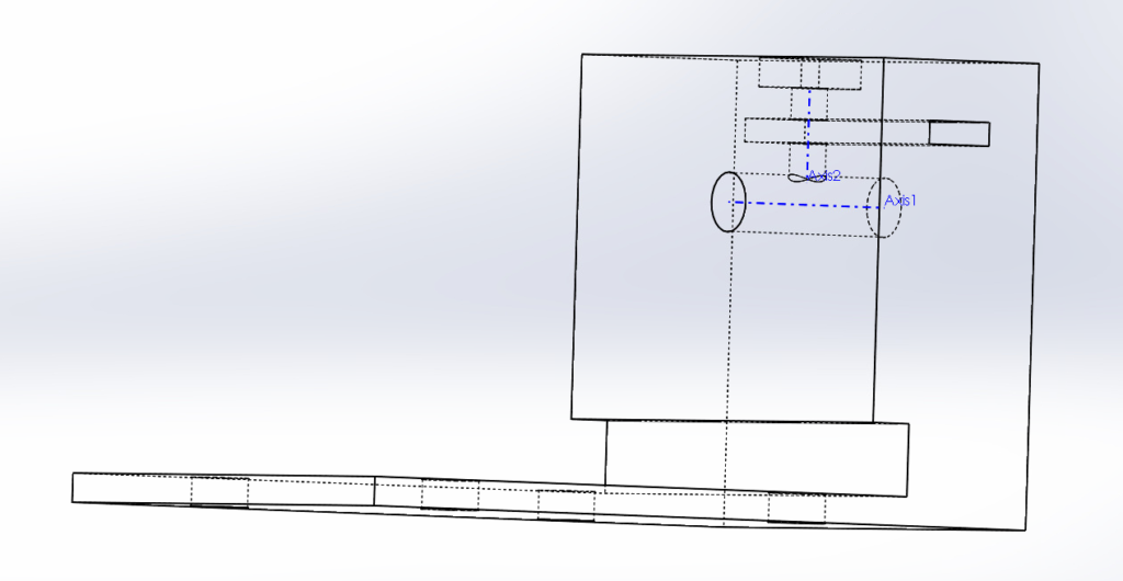
The above photo shows a transparent version of the revised LIDAR mount. The rectangular channel on the right is where the hex nut slides in, and is then locked in place by the screw that would come through the vertical shaft. I’m using the same hex nuts and screws that I mentioned in my last post, simply because I have them.
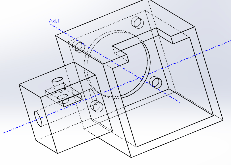
This photo shows a transparent version of the revised Motor 2 mount. There’s a little bit more going on in this photo, so it may be difficult to see clearly. The rectangular channel on the left is for the nut.
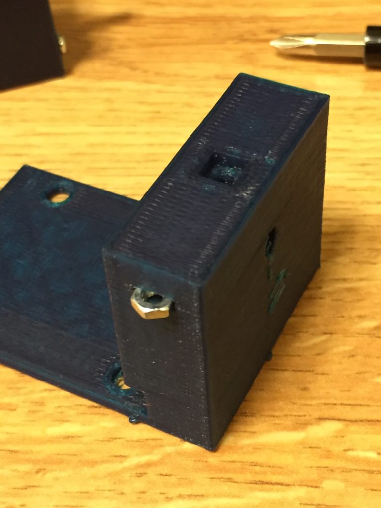
I got both parts printed. When they came back, I discovered that I forgot to account for the margin of error on the printer (~.2mm), and as a result, the hex nut cutouts were too tight. I couldn’t even get the nut fully into the part, let alone as far in as it needed to go.
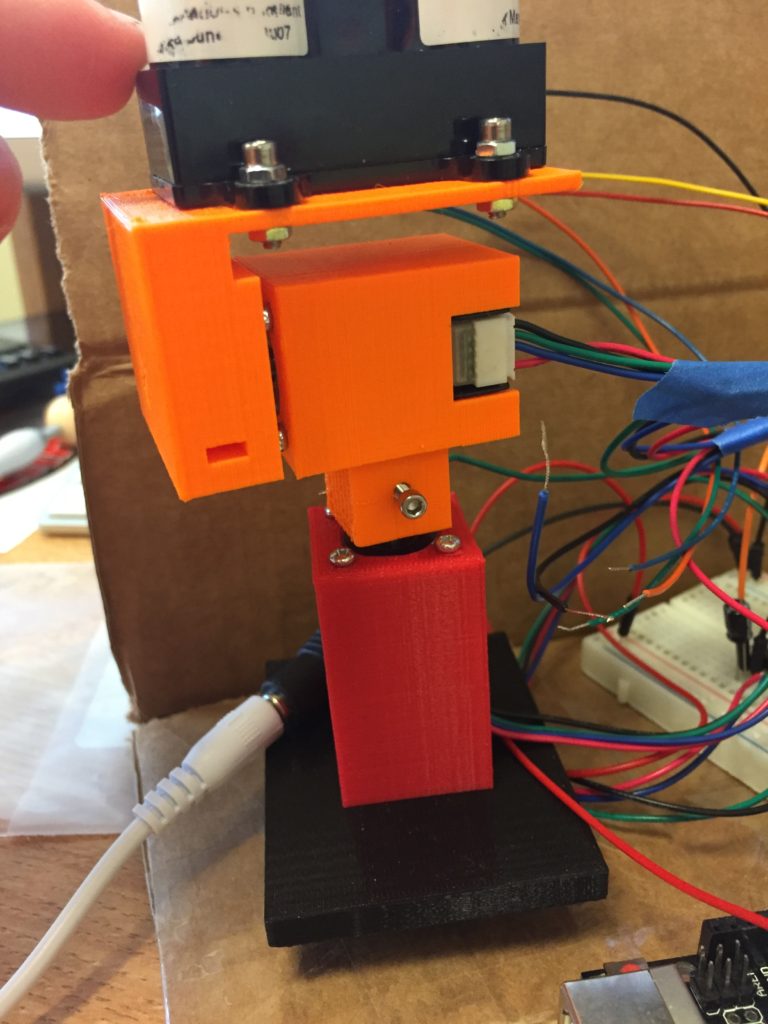
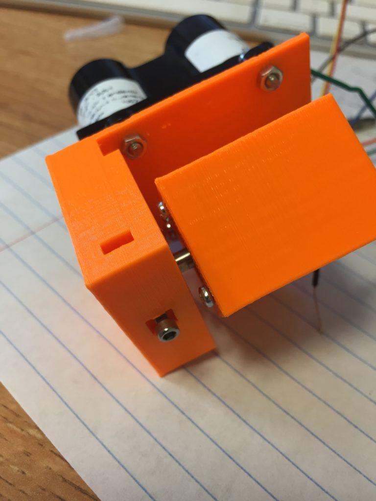
I remeasured the nut and screw and modified the parts to allow enough room for them to fit. I also increased the motor shaft hole diameter a tiny bit on each part – the previous versions were too snug and had to be drilled out. I redrew the screw holes for the LIDAR mount (on the flat face) to make them a little bit smaller and work better within the drawing. The reprints (v4.1) came out perfect! The hex nuts slid in easily, and the nuts and screws hold each other in place. In my preliminary tests since, it seems that the screw will hold each component snugly to its respective motor. The set screws are a little bit too long for this application, and as a result, stick out a little bit. I don’t anticipate this becoming an issue, as it doesn’t seem to interfere with any motion.
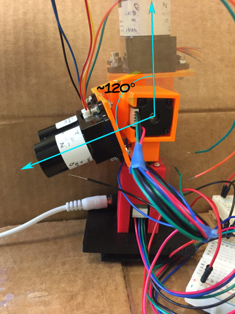
The second motor looks like it will only need an approximate 120 degree range from it’s resting position to vertical. Since motor 1 will spin it around the z axis, once the LIDAR reaches the vertical position, it will have scanned it’s full field of view. This note will become more relevant as I continue with the wiring and programing.
