I started working on this project with Justin Albrecht in the middle of the Spring 2020 semester. With the busyness of the semester and its abrupt COVID interruption, the project (and its documentation here) were put on hold. This post will therefore serve as a (much delayed) intro to the project and overview of what we have accomplished so far.
The Project
Several years ago, Justin created a Rubik’s Cube solving robot as part of his DCC Capstone. That robot, Cubert 1.0, serves as both the inspiration and foundation for this successor project. This iteration will be Raspberry Pi based and improve upon the original design.
The code and other resources related to this project are (and will continue to be) housed on Github at https://github.com/jaybrecht/cubert2.0.
Image Capture and Color Identification
We started with photos of our cube and built some code in Python to identify the colors of each square. From there, we could create a digital representation of that face of the cube. At this point, we only had phone photos of the cube, which we knew would later be replaced by Pi photos. We didn’t waste much time pretending these photos (or their corresponding color filters) would remain valid for long. To save time, we photoshopped the cube face photo (below) to simulate other cube faces without worrying about additional faces or valid configurations.
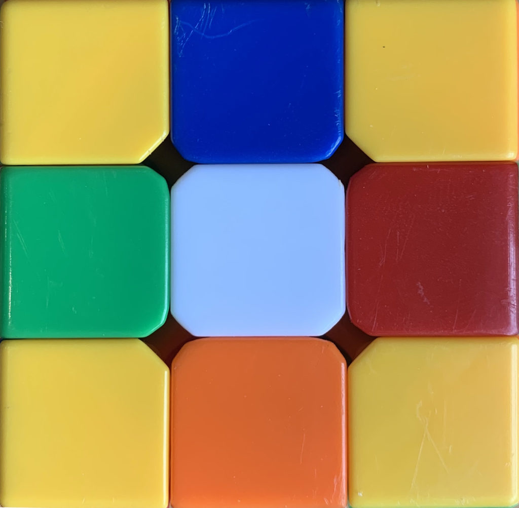
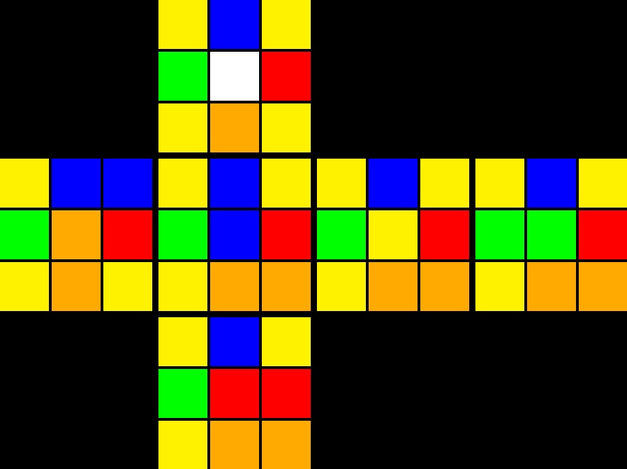
This code utilizes a series of HSV threshold values (experimentally chosen) which are used to generate 6 binary images. Each binary image is divided into equal ninths. By counting the non-zero pixels of the binary ninths, we can determine which belongs to which color. To verify that the face(s) are correct, the program generates a net of the cube (image above) and displays it to the screen. The colors of each face are then written to a text file, with each line representing the center color of that face. An example export of a solved cube:
w: w,w,w,w,w,w,w,w,w
r: r,r,r,r,r,r,r,r,r
b: b,b,b,b,b,b,b,b,b
o: o,o,o,o,o,o,o,o,o
g: g,g,g,g,g,g,g,g,g
y: y,y,y,y,y,y,y,y,y
We made a function to read in this file and store the cube faces in our own data structure.
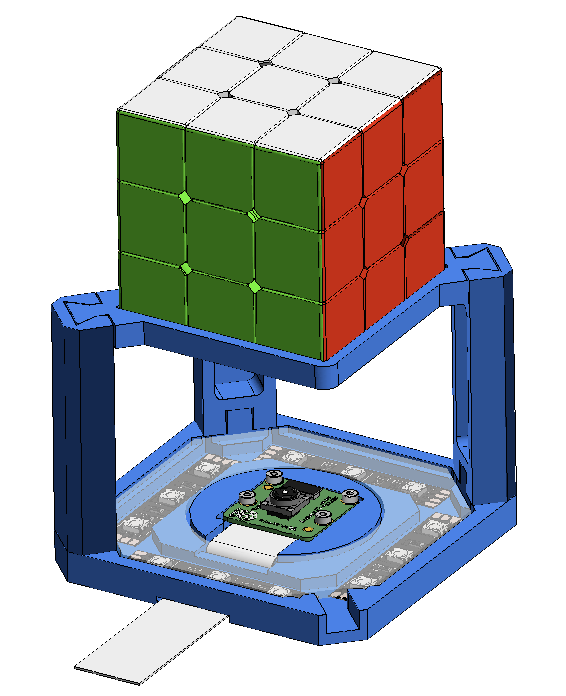
Camera/Lighting Rig
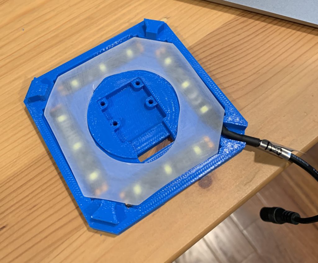
Justin designed a simple mount that integrated the Pi camera, several strip LEDs (for consistent lighting) and a stand for the cube.
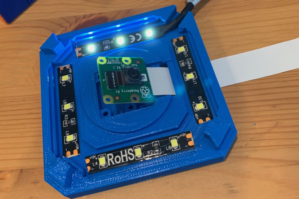
The stand legs attach via a dovetail connection.
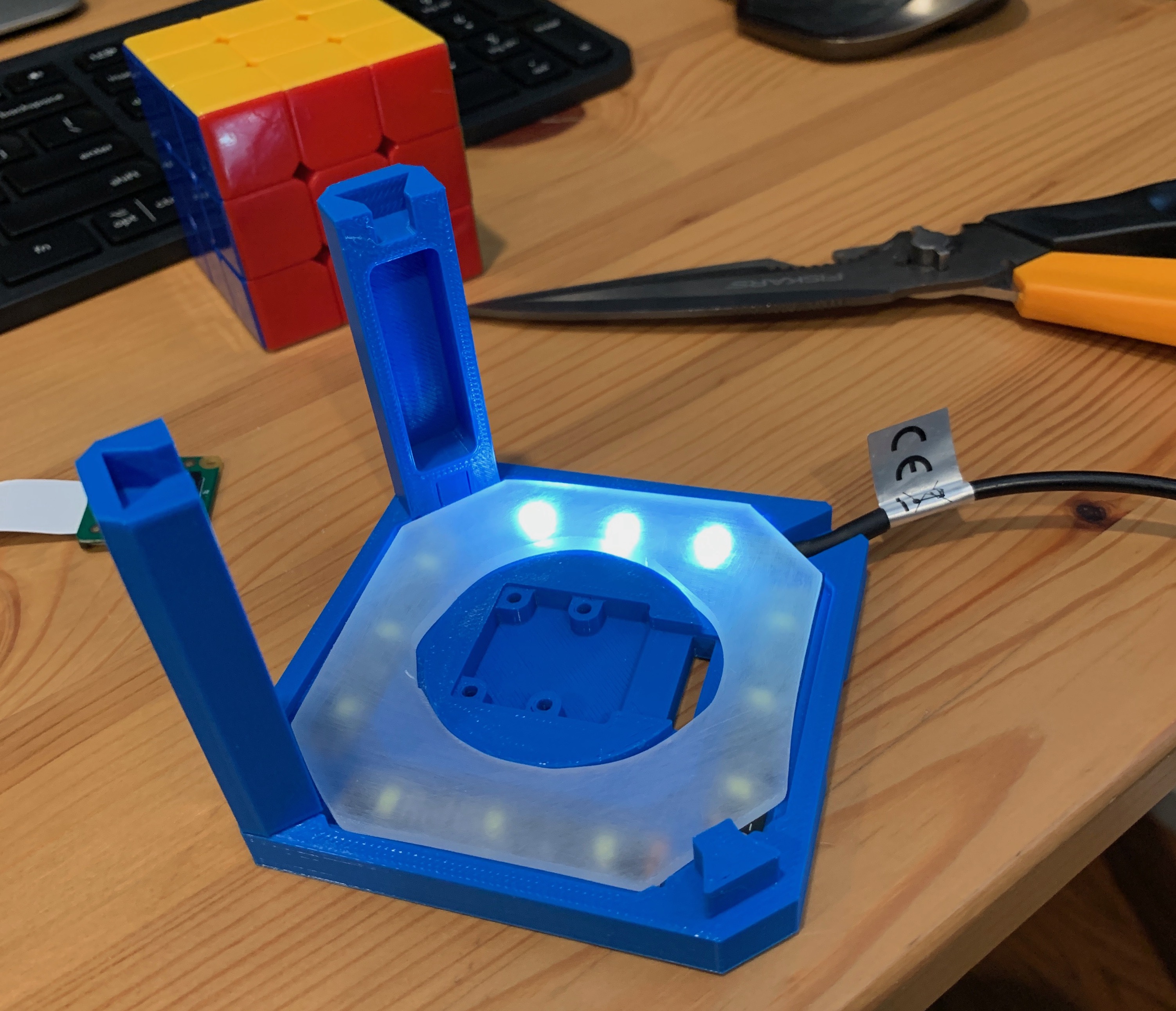

The reflective glare of the LEDs on the shiny cube face is problematic. We’ll need less harsh lighting or a better diffuser later.
Gripper Assembly
Justin’s put a lot of work into designing and modeling the gripper assembly for the cube solver. The design involves four grippers/claws (I’ll be using gripper and claw interchangeably). Each gripper is opened/closed via a servo actuated rack and pinion gear. The gripper/claw, when closed, rotates the face of the cube, and is actuated by a stepper motor (likely a NEMA8). The stepper/servo/claw assembly needs to retract from the cube (to allow for other motions) and will be withdrawn via a small solenoid. 3 actuators per gripper x 4 grippers makes this a 12 actuator system. Below is an early video of the rack and pinion system.
This design has evolved considerably since these screenshots were taken, but these serve to give you an idea of the early stages of the design. Below are some much newer renders that show most of the current design. Note there is an additional gear attached to the servo that is not shown.
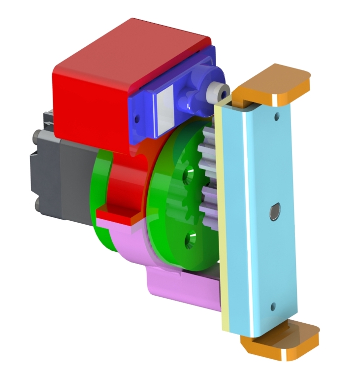
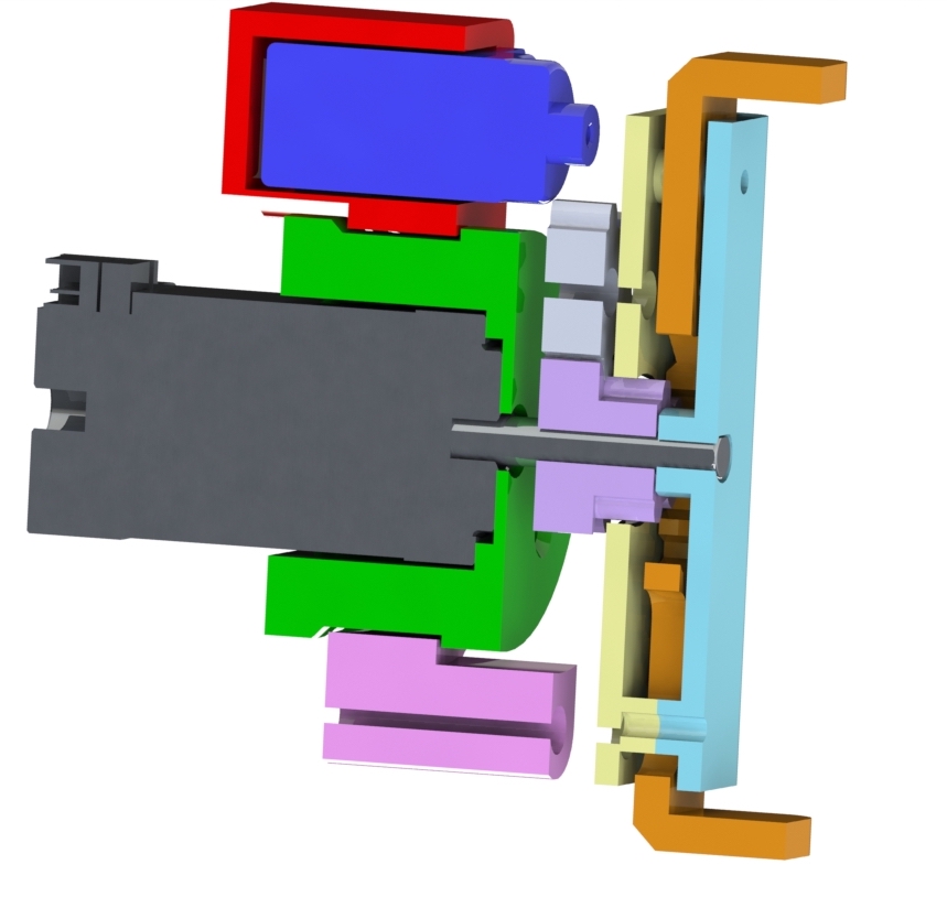
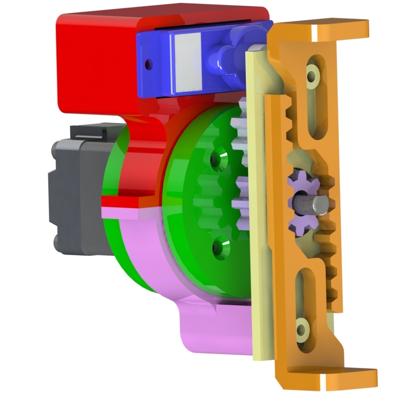
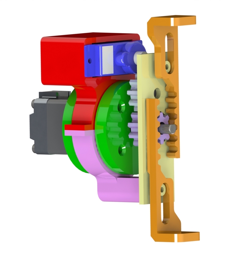
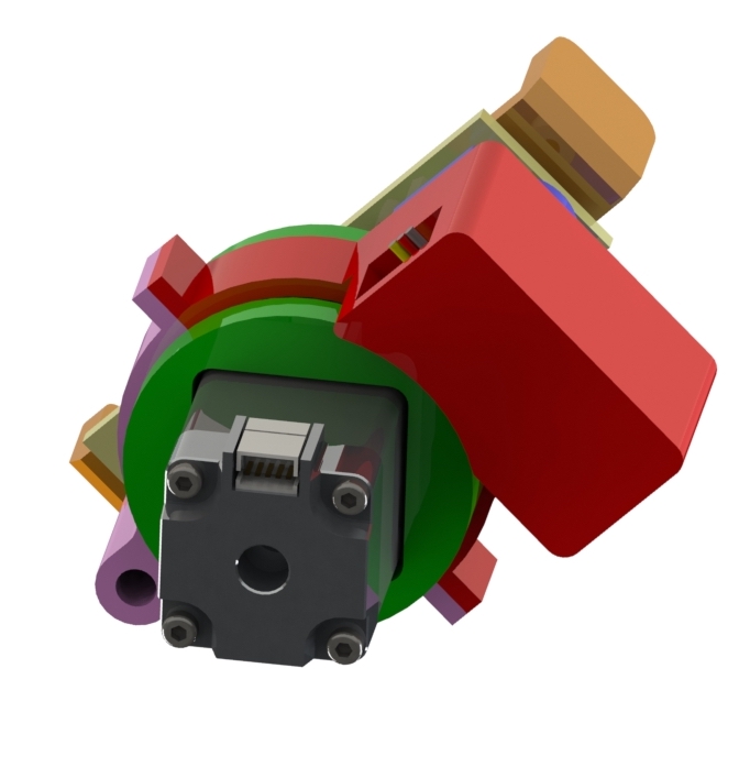
Rendered view of the servo assembly rotated around the stepper motor 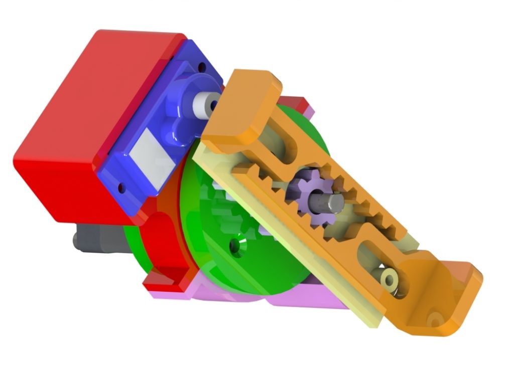
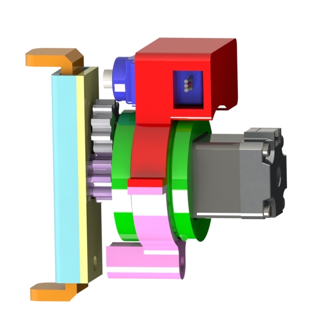
Alternate view of the rotated assembly
The servo housing (red/pink) rotates around the stepper housing (green) as the stepper turns. Bearings in that interface will facilitate this motion. This entire assembly will be mounted on rails and moveable away from the cube via a solenoid.
PCB Design
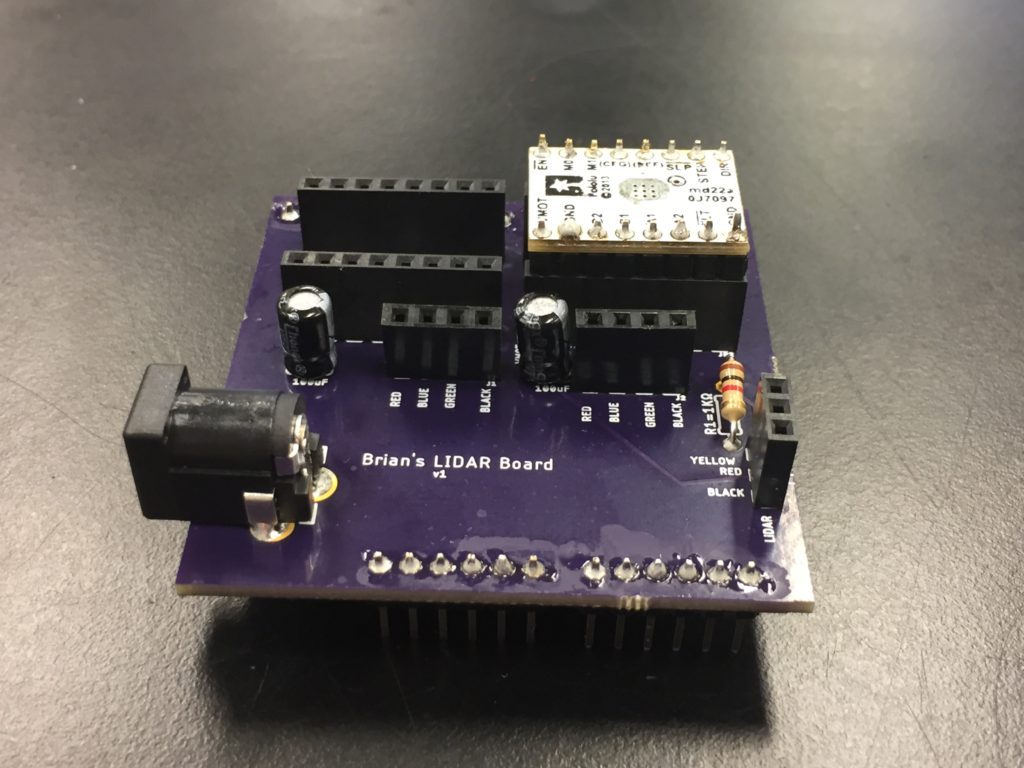
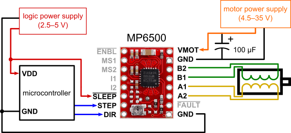
With limited access to SolidWorks (for the time being), I’ve focused on the electrical design in Eagle instead of the mechanical design. I knew we’d need 4 stepper drivers, one for each stepper motor. I’d integrated stepper drivers into a PCB in my previous LiDAR project. The easiest way to do so, I found, was to mount two 1×8 female pin headers, and then seat the driver on top. This allows easy swap-out of the stepper driver if it gets damaged or burnt out, or if there is a second iteration PCB.
After re-familiarizing myself with Eagle (and with help from several great SparkFun guides), I began drafting a schematic that satisfied the connections we thought we needed. Eagle’s name/label tools were very helpful in keeping this neat and organized.
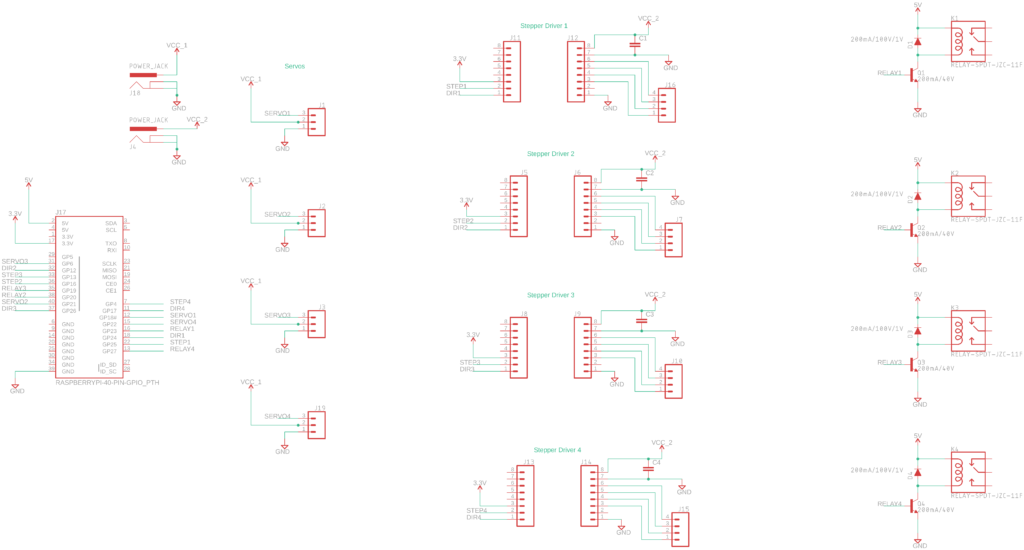
In this early rendition, I borrowed heavily from my past PCB design. Each actuator (with male headers) connects to the system via a matching female header. Justin suggested we adopt better industry practice and combine each of the actuator’s leads into a single molex style crimped connector. There would be 4 bundles of wires (one for each actuator), terminating in a male molex connector, which would connect to the control board via a matching female molex connector. While modifying the schematic and board to accommodate new connectors (larger-than-required 16 pin connectors, as a placeholder) I realized that the relay circuit for the solenoid was unnecessarily complex. Borrowing from the Arduino schematic for the solenoid we had selected, I redesigned that portion of the circuit. It now uses a transistor and Schottky diode to actuate each of the solenoids.
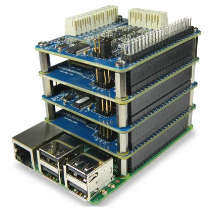
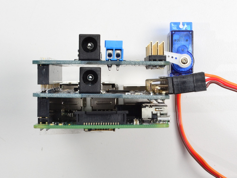
Without the relays, the circuitry takes up less space. These two previous designs utilized a GPIO ribbon cable and matching shrouded header to connect the Pi to the assembly. I recently realized there might be sufficient space to redesign the board as a Pi shield/Pi hat. I spent some time rearranging the components. The 16 pin molex connectors take up a lot of space, and there isn’t room to have the control circuitry and the connectors on the same Pi sized board. It occurred to me (based partly on the two examples below), that we could create a stacked board – the layer atop the Pi would house the control circuitry and the layer above it would house the connectors. The two boards would be supported by standard standoffs.
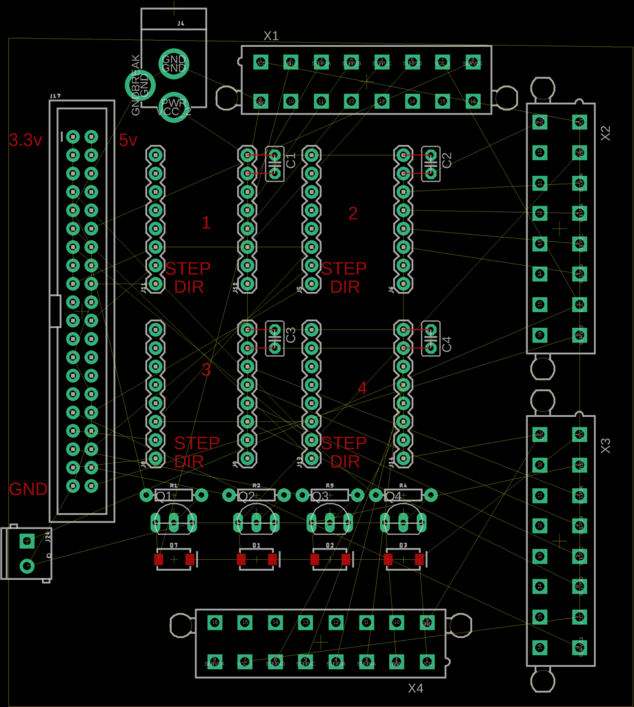
At the current design, I think we need ~30 pins to pass through between the two layers (1 servo signal, 4 stepper signals, 2 solenoid wires, x4 + VCC and GND). This fits nicely within a matching 20×2 header pin (like the Pi has). The revised design looks something like this:
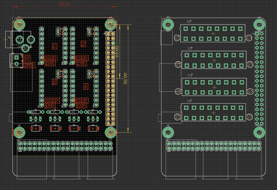
It seems that Eagle only supports one board/file, so I split the project into two files and started experimenting with different layouts and configurations.
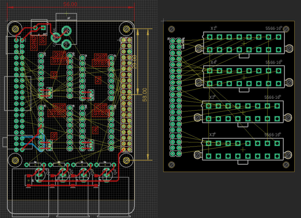
This current configuration seems very difficult to route (and maybe not even possible – Auto router maxed at ~67% complete). I’ll need to play with the layout (and likely also the pin-outs) to make it more feasibly routable.
To complicate matters further (part of the inspiration behind the larger than necessary molex connectors) is the potential requirement for additional components. To zero the stepper motors (which, unlike servos, carry no knowledge of their own position), we’ll likely need either limit switches or T-slot photo interrupters. When the system starts up, it will need to rotate each stepper until these are triggered, so we know the steppers’ positions. Other, unforeseen components may also need to be incorporated as the project evolves.