Happy 2021! If you haven’t read my first post about the Cubert project, you can read it at https://brianbock.net/2020/07/19/new-project-rubiks-cube-solving-robot/
Justin did a bunch of work in the past week or so and redesigned the claw mechanism in Fusion 360. We don’t need the positional precision of the rack and pinion claw; it just needs to open and close. Justin reworked this mechanism for a simpler cam. The cam, mounted directly to the servo head, rotates and pushes the spring loaded claws open. To close, the cam returns to its zero position and the springs push the claws back down.
Click on any of the images to see them full size.
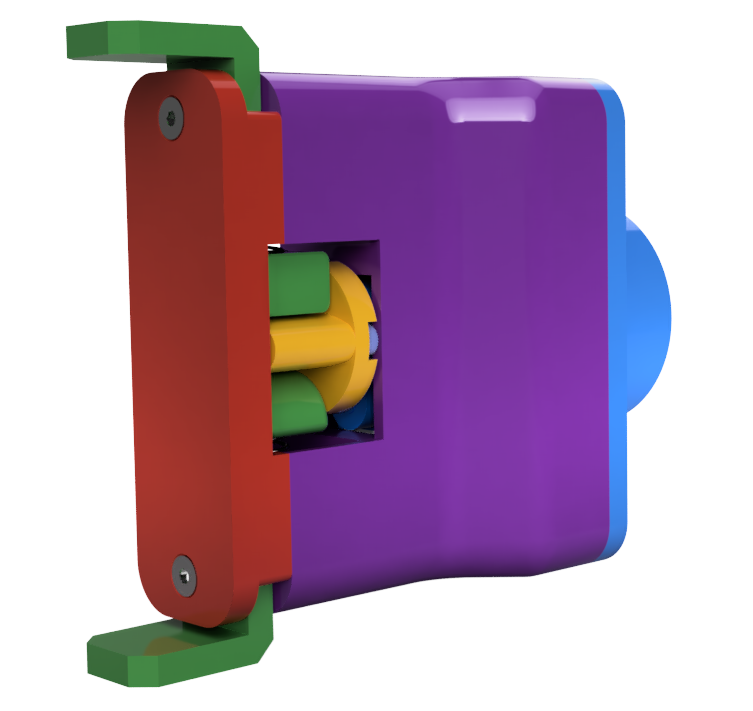
Render of the cam actuated gripper 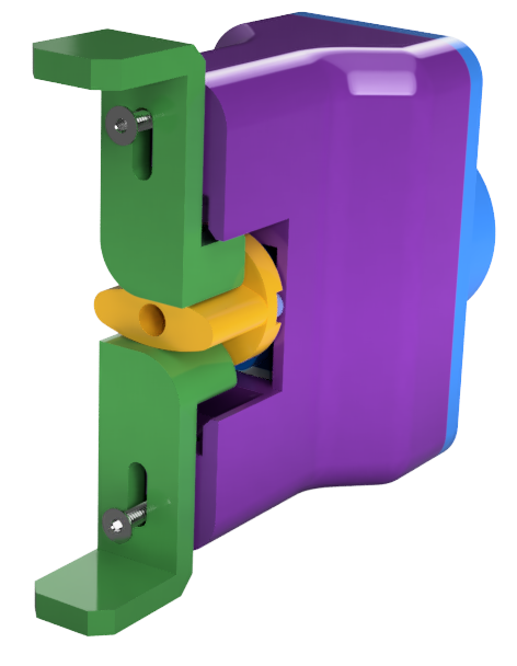
Render of the cam actuated gripper without the front plate 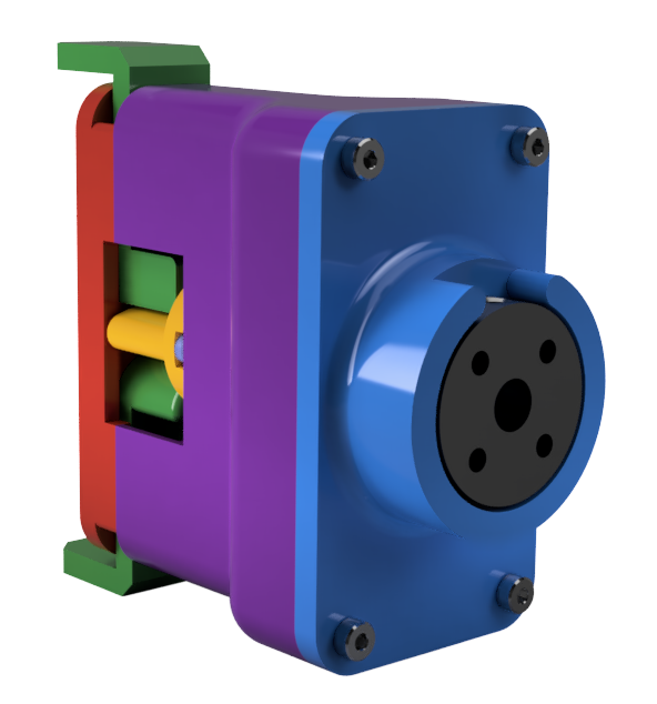
Render of the rear of the gripper, showing the stepper interface
I printed this first physical prototype. When the parts arrive from McMaster, I’ll assemble it all and test the fit and cam/spring mechanism.
We had previously planned to retract each claw with a solenoid. (Remember, the claws need to retract so they don’t get in the way of other claws turning the cube or rotating a face.) The solenoids drive up our current requirements and may not provide particularly precise (or smooth) motion. The new plan is to replace the solenoid with either a lead screw or a rack and pinion. The lead screw option is appealing because it’s compact and straightforward. However, we only need a few inches (likely less than 3) of retraction travel. Most commercially available lead screws we can find come in much longer lengths, and are expensive to source (especially in short lengths). We could cut a long lead screw into several smaller screws, but that will ruin the threading on both ends of each length, making them harder to work with. The rack and pinion, by contrast, is easily customizable – it’ll be designed and 3D printed with most of the rest of the assembly.
The face turning motor is currently a NEMA 14. We’ll likely swap it for the smaller NEMA 8 stepper motor. The rack could be along the underside of this motor. I don’t think we’ll need much more travel than the length of the motor. What we actuate the pinion with is another consideration. A DC motor (which just spins) has no positional control, and we’d want to move the pinion by a controlled amount. A stepper motor would work, but it requires a separate control board to drive, and without any intrinsic positional knowledge, would also require at least one zeroing limit switch. Certainly doable, but adds some additional complexity (and cost) that we’d probably want to avoid. A servo would work if we can get the rack travel we need with less than 180 degrees of pinion rotation (most servos have a +/- 90 degree range). That serves to specify our pinion gear radius. Servos tend not to be very quick, which will limit the functional speed of the full robot (and Rubik’s cube solve). Continuous servos, which rotate without limits, have the same issues as the DC motor and stepper, requiring something to gauge/control position.

Render of the assembled rack & pinion retractor 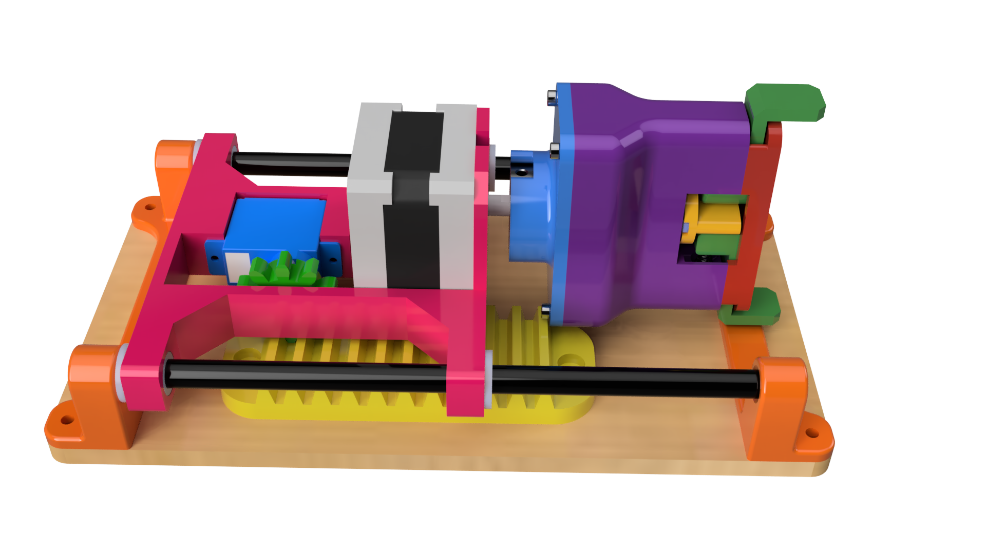
Render of the assembled rack & pinion retractor 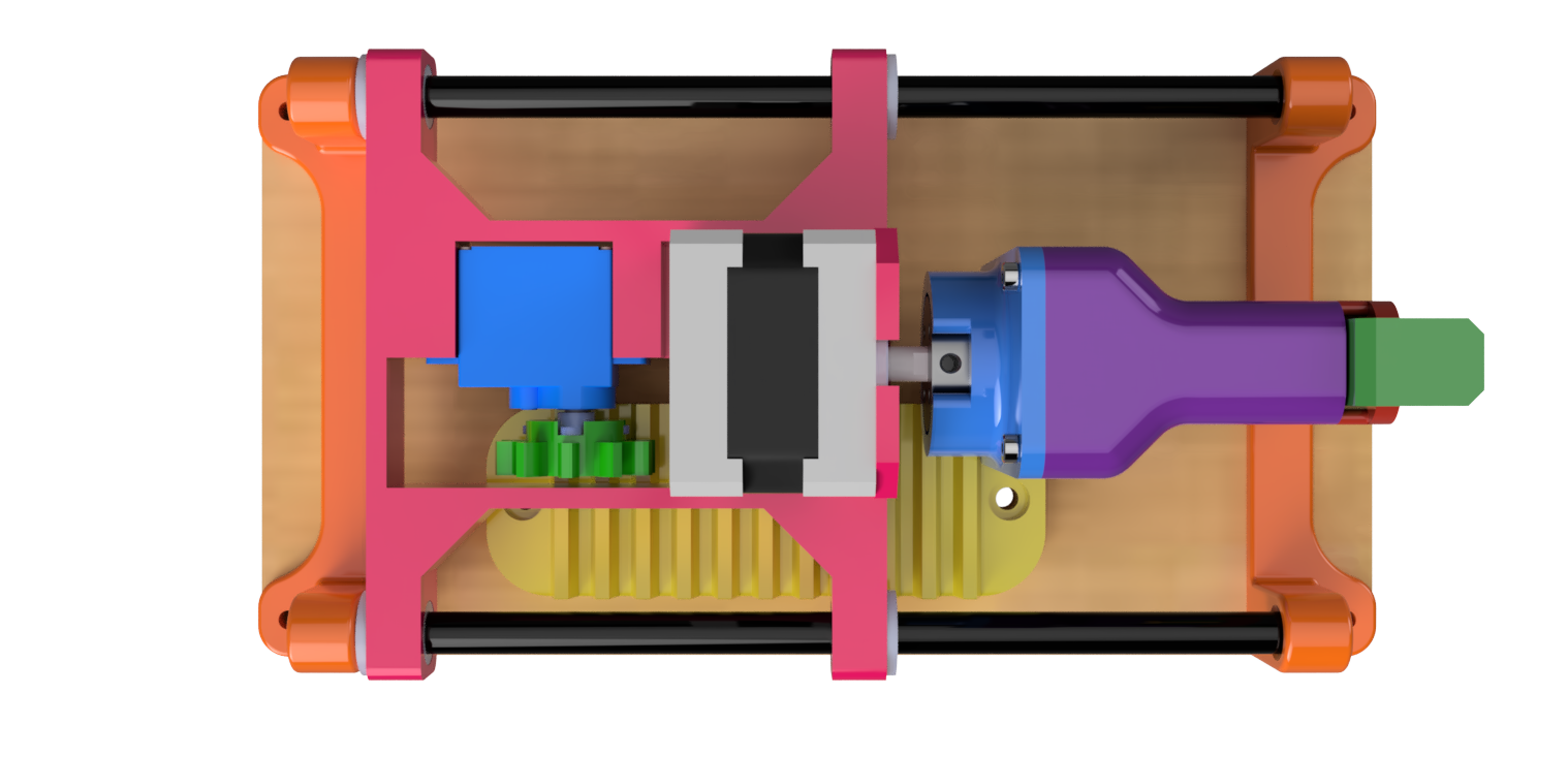
Top view of the assembled rack & pinion retractor