If you haven’t read about this project yet, check out my previous post.
Getting the servo pinion to mesh with the rack proved more challenging then it should have been. I used a GrabCad micro servo model as a placeholder for my physical servo in the digital model. Unfortunately, this model differed (just by a few mm) from the physical servo I have. This discrepancy made the servo alignment difficult. The photo below shows this problem (in SolidWorks, the digital servo’s gear aligned with that blue center line).
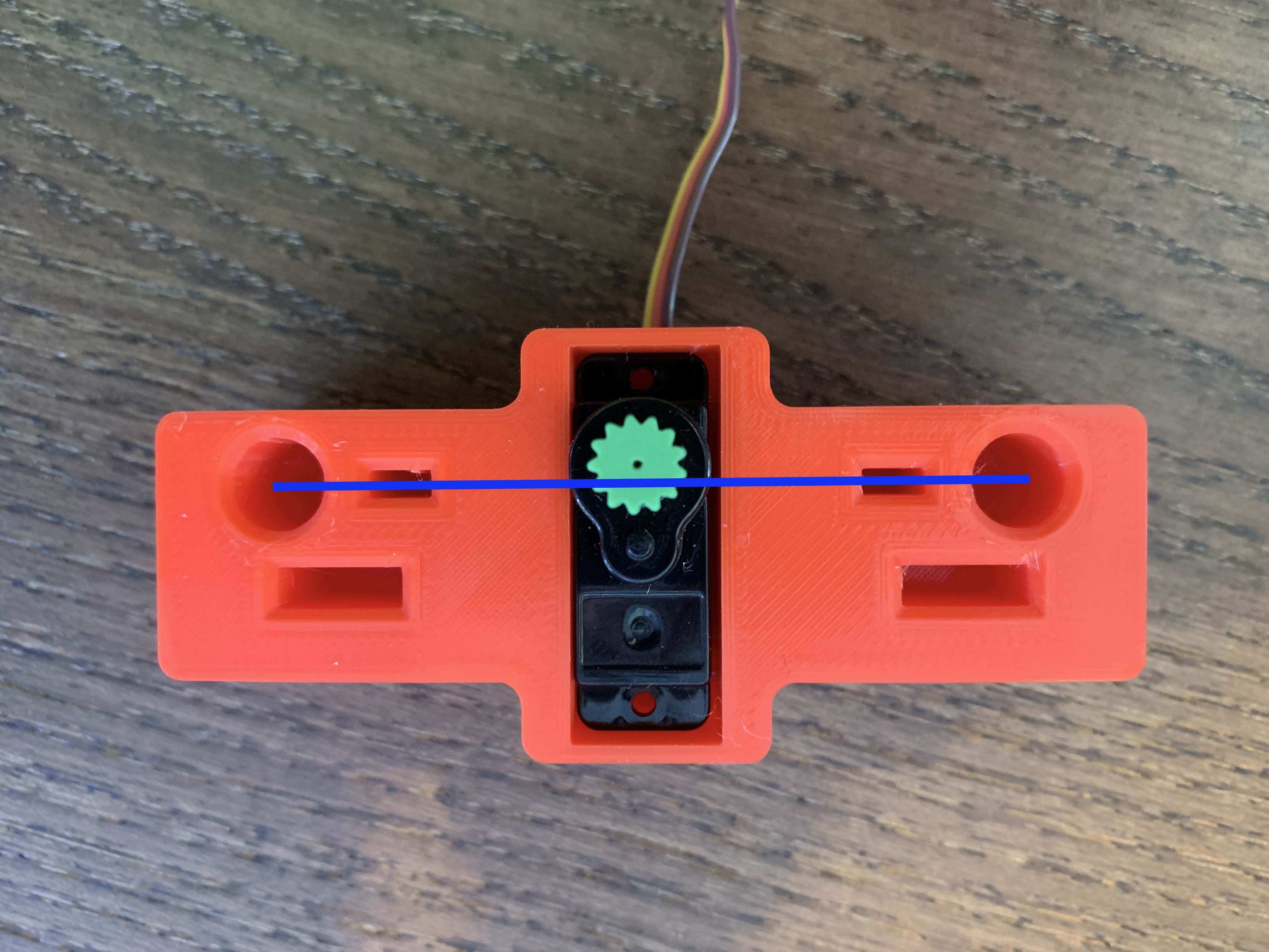
We’ll get back to that servo alignment issue in a moment. Let’s first revisit my plastic skull:
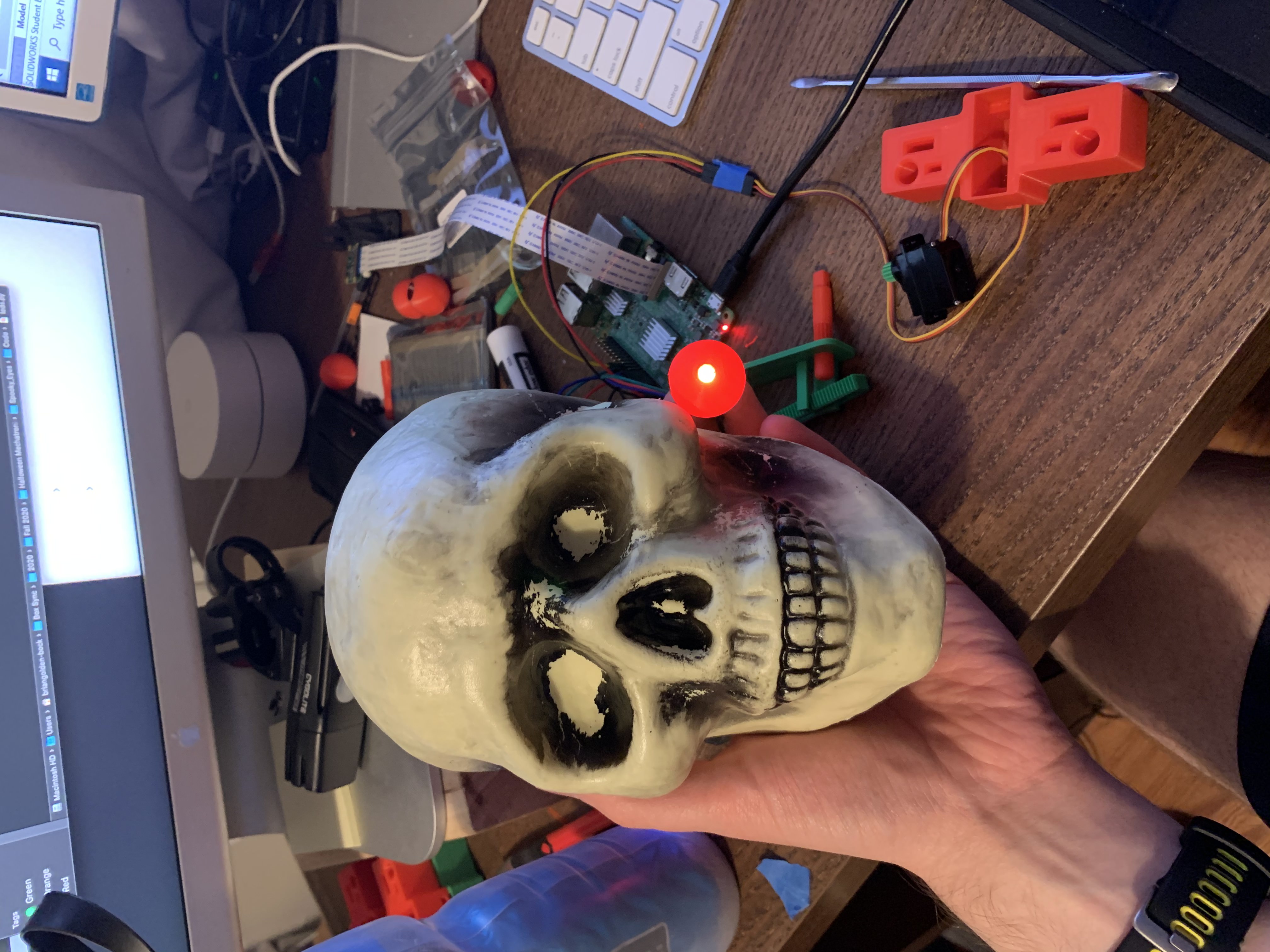
I think I want to call this skull Yorrick
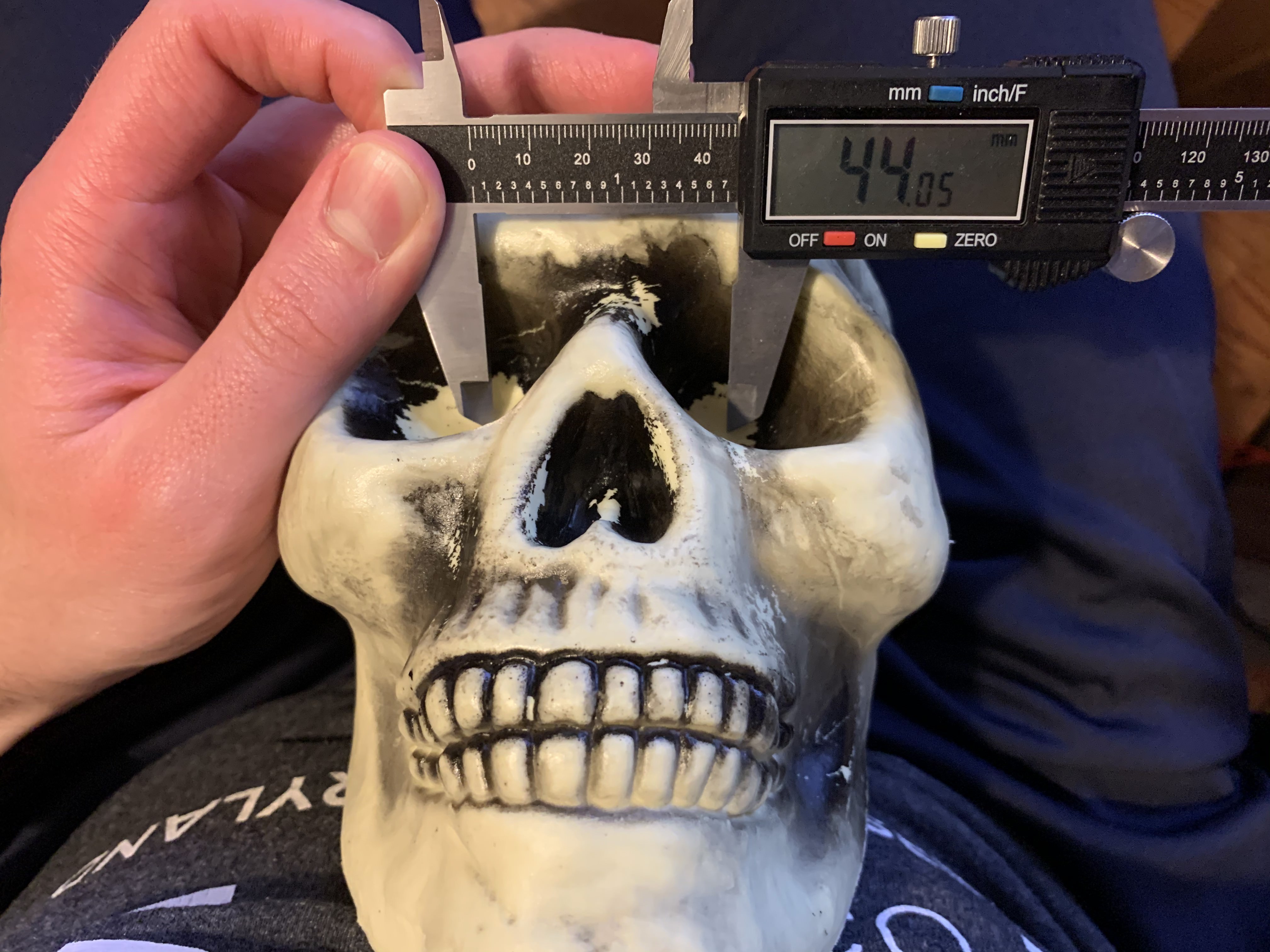
Unfortunately, the interpupillary distance (IPD) of the skull is smaller than that of my own eyes (which I had used as an approximate IPD previously). Fortunately, being both dead and made of plastic, the skull had no qualms about me stabbing it’s face with my sharp calipers to get this measurement. Calipers are sharp and belong no where near anyone’s eyes! Do not attempt to use calipers to measure your own IPD.
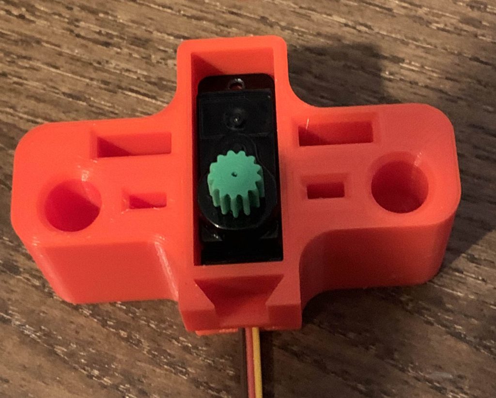
I needed to reprint the base to improve the servo alignment, so I took this opportunity to redesign the system to be more compact. I took a few minutes to create a well measured digital model of my own servo, and swapped out the GrabCad model. The new base, rack, and mounting plate are fundamentally the same design, just much closer together. I knew I’d soon also want to integrate the camera (hidden in Yorrick’s nose), and wanted to leave flexibility in the design to include that. However, I was getting tired of printing iterations of the base (now 6+ minor iterations in), so I modified the base to have a dove-tail interface on the front. By a happy coincidence, it seems that the position of the edge of the base should align closely with the nose.
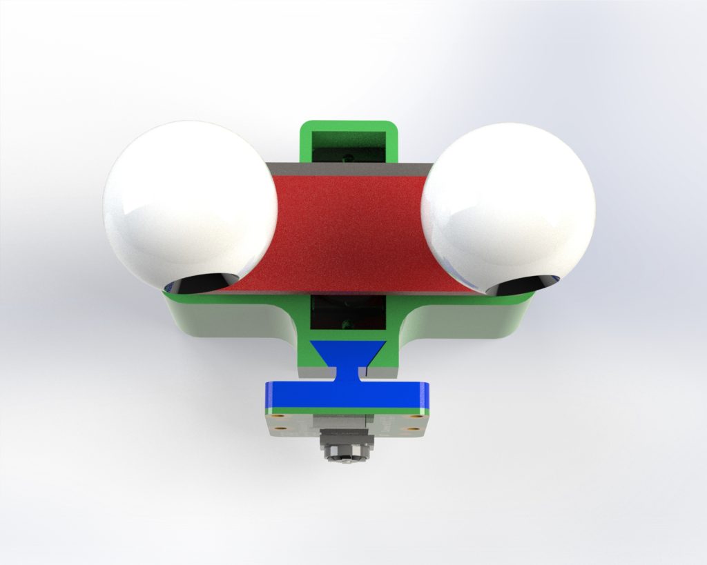
Pi camera model
I printed a quick test of this connection to ensure the parts would fit well, and then printed the camera mount. Fortunately, I had some left over brass inserts and matching screws from my 360 Camera capstone project, which I used to attach the camera to the plate. The holes I modeled for the inserts came out a tiny bit too small, so I used a hot soldering iron to push them in.
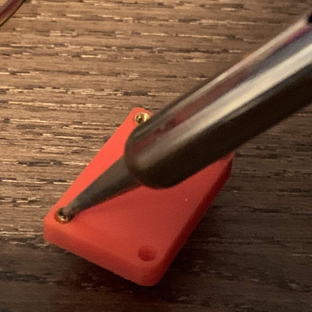
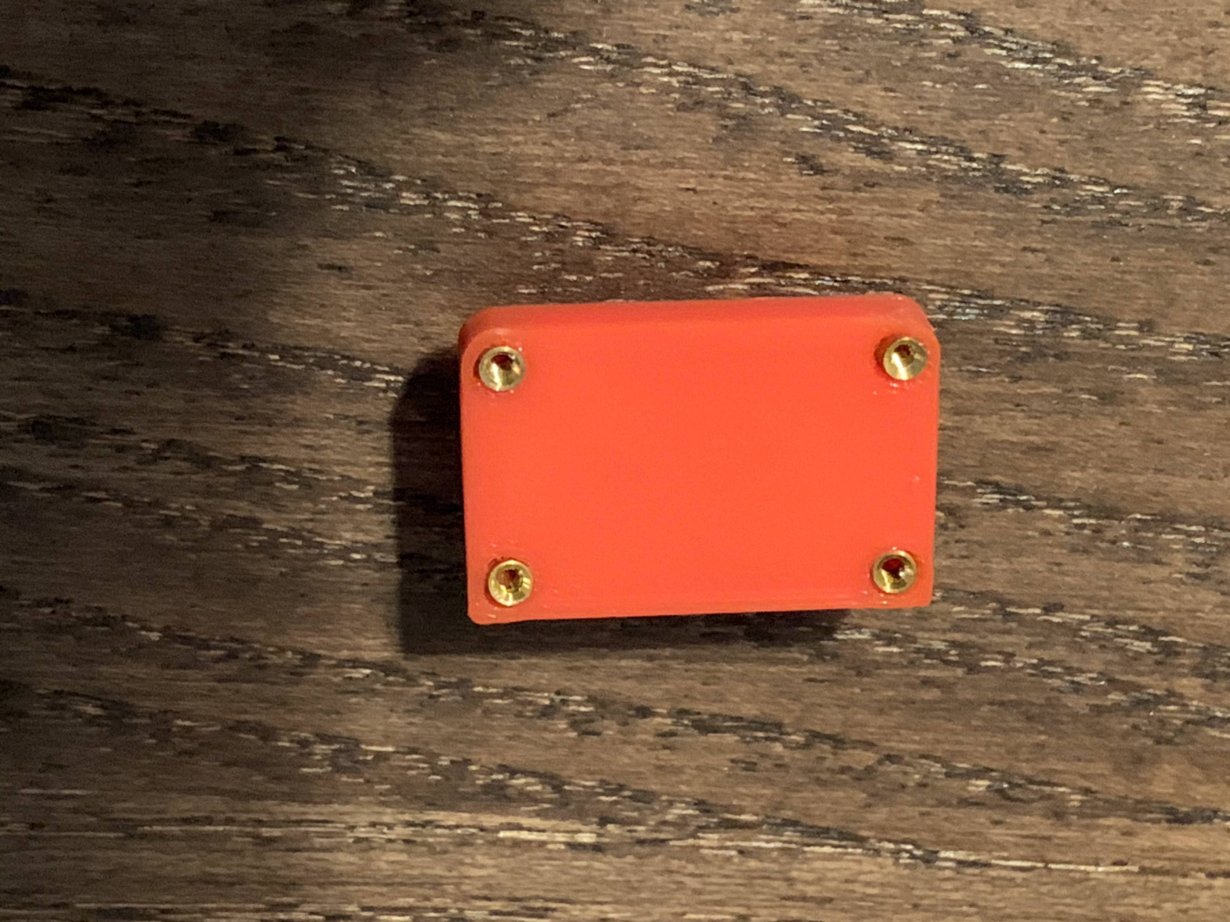
The soldering iron made inserting the inserts easy, although the high heat made them slide in slightly askew. I’ll have to reprint this part with better hole sizes so all the inserts can be parallel.
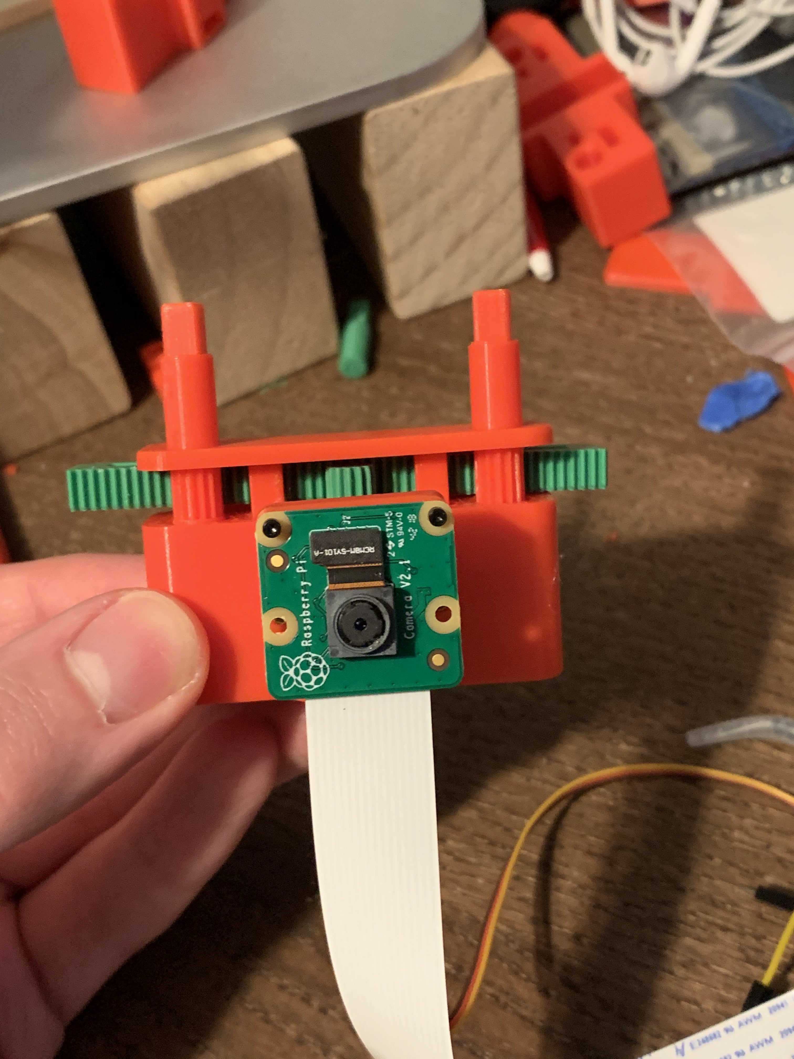
Finally, the servo meshes perfectly with rack, and the eye action works well. In the video below, I’m alternating between +/- 90 degrees in the servo.
Now that the hardware all works, let’s go back to the skull. Time to cut the skull open (along the convenient injection molding half seam).
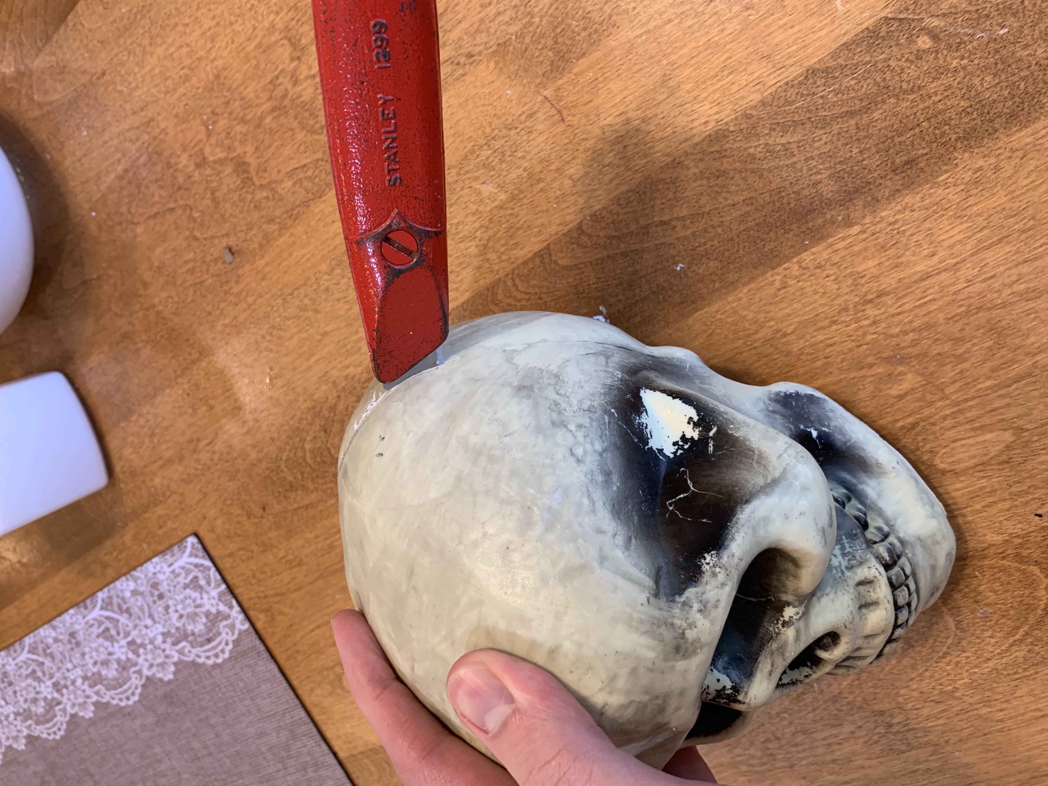
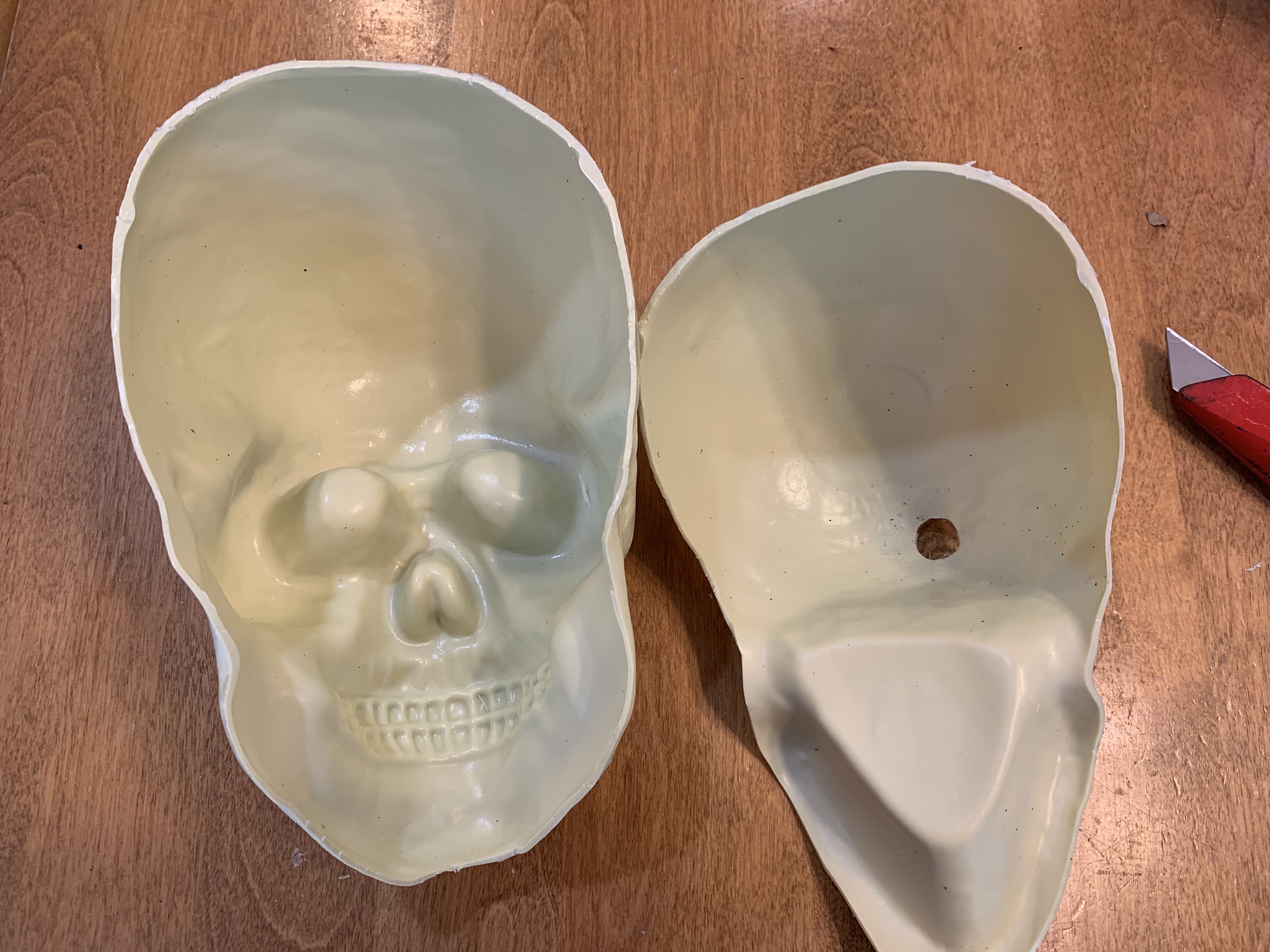
Now with the inside of the skull accessible, it’s time to drill out the eyes. Drill bits belong nowhere near human eyes! Do not try this at home

The eye holes are still too small, even after using a 1/2″ drill bit, which is the largest drill bit in most drill bit kits. Fortunately, I also have a 3/4″ drill bit.
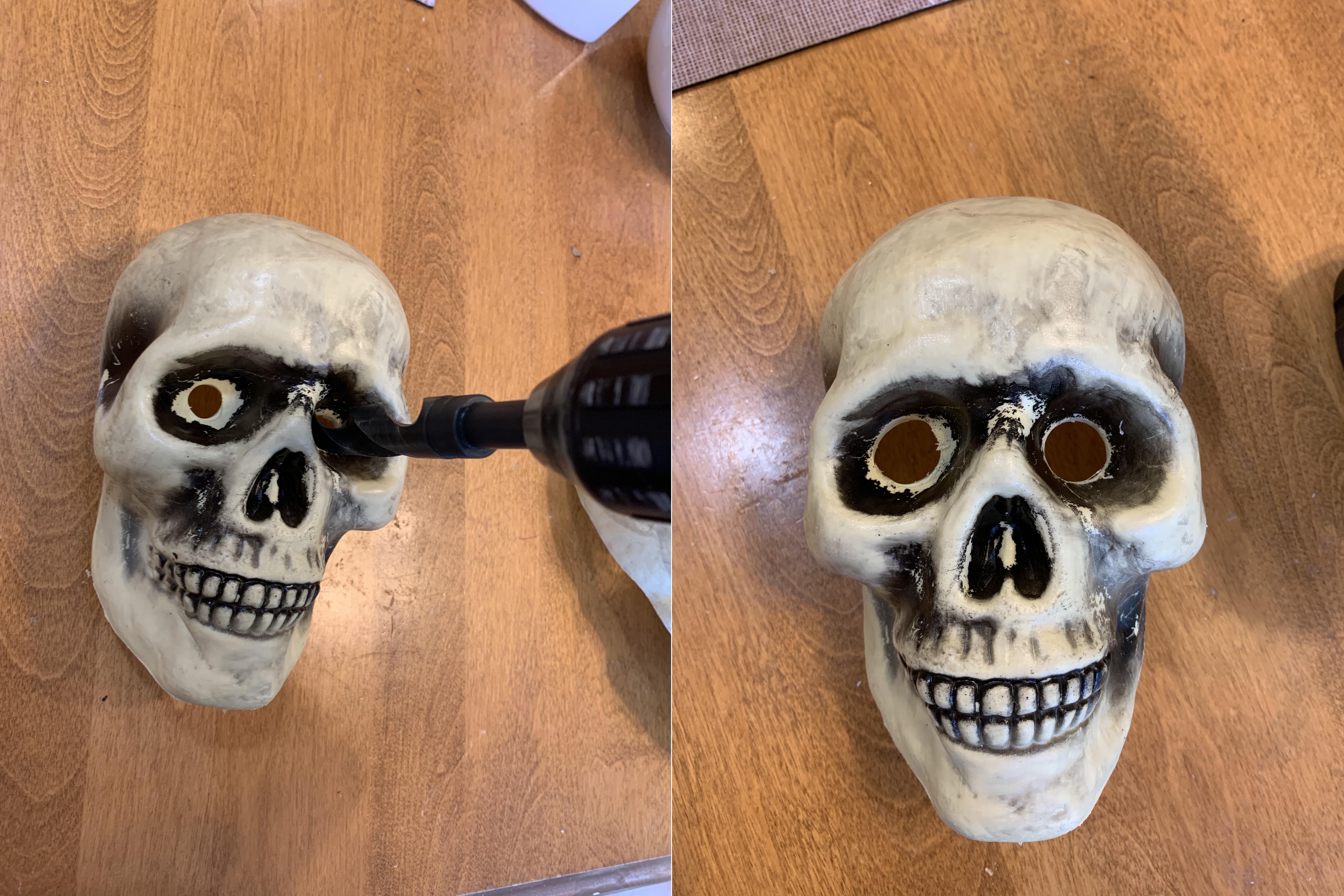
The eye holes are still too small to have the eye balls on the opposite side, but that’s the biggest drill bit I have. Or is it? Turns out no – I have a comically large conical step drill bit, whose original purpose I can only guess. Most of this drilling (despite the photo below) was from the other side of the skull.
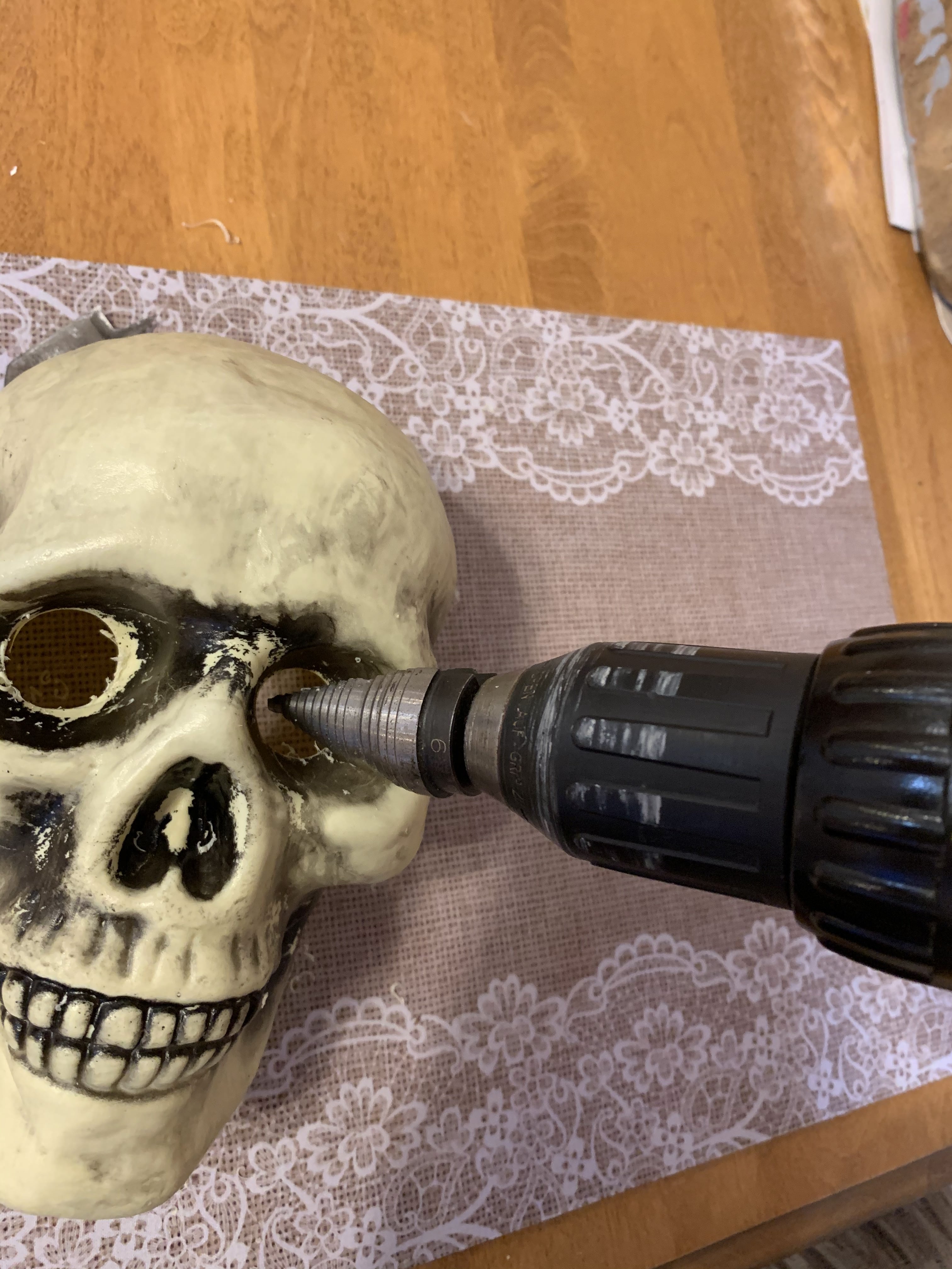
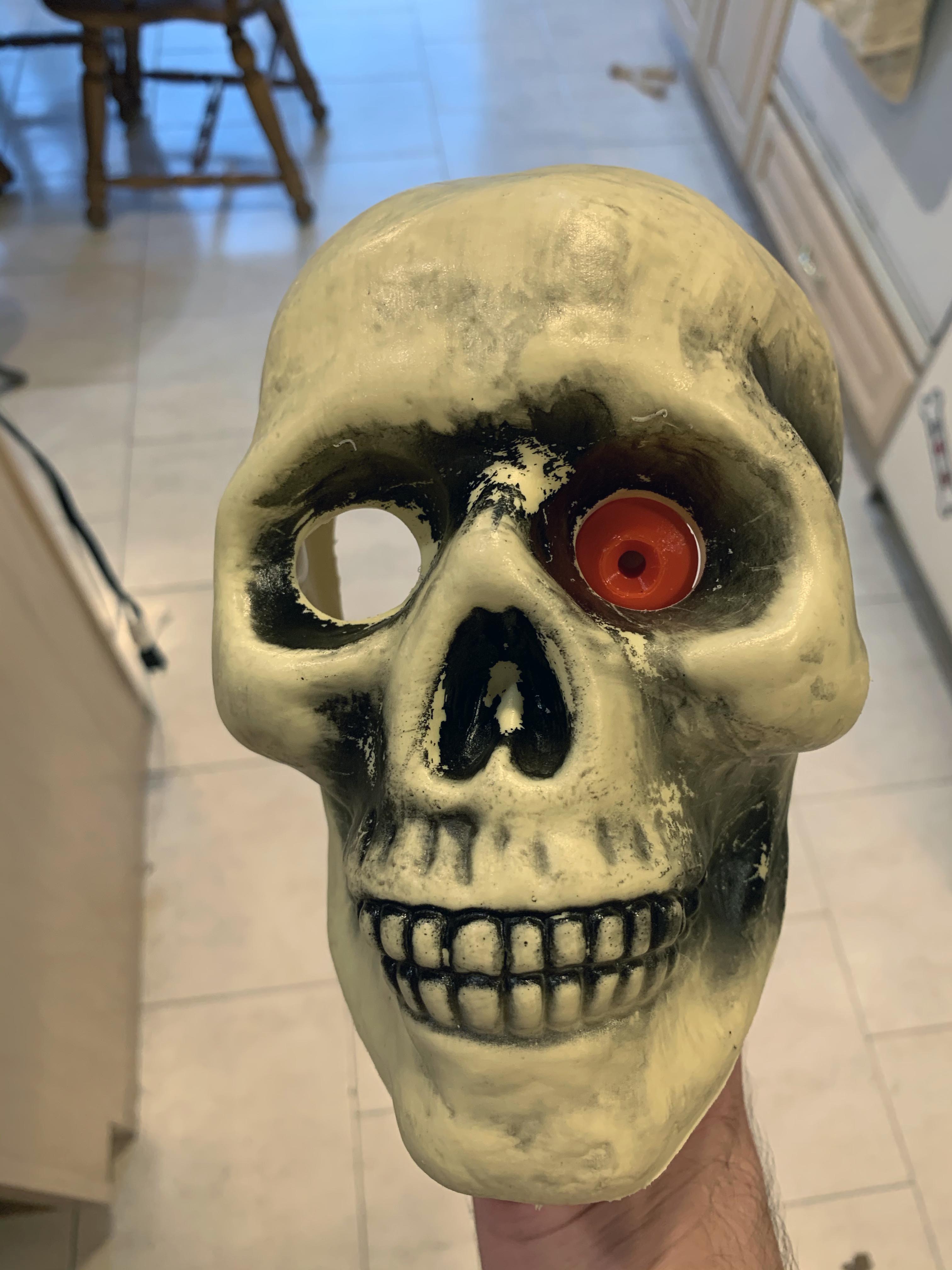
Now we’re getting somewhere! The eyes look proportionate in their sockets. I can’t make the holes much bigger because the right eye (from the skull’s perspective, left in the image above) socket is slightly elliptical, and I worry if I make the holes much wider, this deformity will become obvious.
More to come on this project soon. Up next I need to drill a small hole in the center of the nose for the camera, and then begin working on software.